Yokogawa EJX930A User Manual
Page 15
<2. Handling Cautions>
2-4
IM 01C25R03-01E
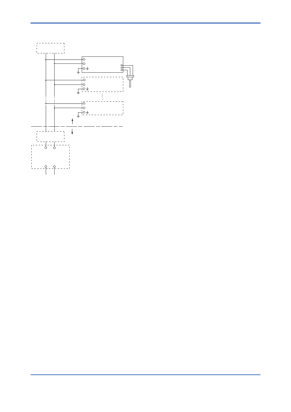
● Installation Diagram for Nonincendive
(Division 2 Installation)
Non-Hazardous Location
FM Approved
Associated Nonincendive Field
Wiring Apparatus
Vt or Voc
It or Isc
Ca
La
Hazardous Location
F0203.ai
Terminator
General Purpose
Equipment
Pressure
Transmitter
SUPPLY
Terminator
+
–
Transmitter
+
–
Transmitter
+
–
+
–
+
–
Note 1. Installation should be in accordance with
the National Electrical Code ® (ANSI/NFPA
70) Article 500.
Note 2. The configuration of Associated
Nonincendive Field Wiring Apparatus must
be FM Approved.
Note 3. Approved under FNICO Concept.
Note 4. Dust-tight conduit seal must be used
when installed in Class II and Class III
environments.
Note 5. Associated Apparatus manufacturer’s
installation drawing must be followed when
installing this apparatus.
Note 6. No revision to drawing without prior FM
Approvals.
Note 7. Terminator must be FM Approved.
Note 8. The nonincendive field wiring circuit
concept allows interconection of
nonincendive field wiring apparatus with
associated nonincendive field wiring
apparatus, using any of the wiring methods
permitted for unclassified locations.
Note 9. Installation requirements;
Vmax ≥ Voc or Vt
Imax = see note 10.
Ca ≥ Ci + Ccable
La ≥ Li + Lcable
Note 10. For this current controlled circuit, the
parameter (Imax) is not required and need
not be aligned with parameter (Isc) of the
barrier or associated nonincendive field
wiring apparatus.
Note 11. If ordinary location wiring methods are
used, the transmitter shall be connected
to FM Approved associated nonincendive
field wiring apparatus.
Electrical data:
Vmax: 32V
Ci:1.76 nF
Li: 0 µH
● FNICO Rules
The FNICO Concept allows the interconnection of
nonincendive field wiring apparatus to associated
nonincendive field wiring apparatus not specifically
examined in such combination. The criterion for
such interconnection is that the voltage (Vmax),
the current (Imax) and the power (Pmax) which
nonincendive field wiring apparatus can receive and
remain nonincendive, considering faults, must be
equal or greater than the voltage (Uo, Voc or Vt),
the current (Io, Isc or It) and the power (Po) which
can be provided by the associated nonincendive
field wiring apparatus (supply unit). In addition the
maximum unprotected residual capacitance (Ci)
and inductance (Li) of each apparatus (other than
terminators) connected to the Fieldbus must be less
than or equal to 5nF and 20uH respectively.
In each N.I. Fieldbus segment only one active
source, normally the associated nonincendive
field wiring apparatus, is allowed to provide the
necessary power for the Fieldbus system. The
allowed voltage (Uo, Voc or Vt) of the associated
nonincendive field wiring apparatus used to supply
the bus cable must be limited to the range 14Vdc
to 17.5Vdc. All other equipment connected to the
bus cable has to be passive, meaning that the
apparatus is not allowed to provide energy to the
system, except a leakage current of 50 µA for each
connected device. Separately powered equipment
needs galvanic isolation to ensure the nonincendive
field wiring Fieldbus circuit remains passive.