3 logical structure of each block, 4 wiring system configuration, Logical structure of each block -2 – Yokogawa EJX930A User Manual
Page 23: Wiring system configuration -2, Fieldbus, Sensor ejx multivariable transmitter
<3. About Fieldbus>
3-2
IM 01C25R03-01E
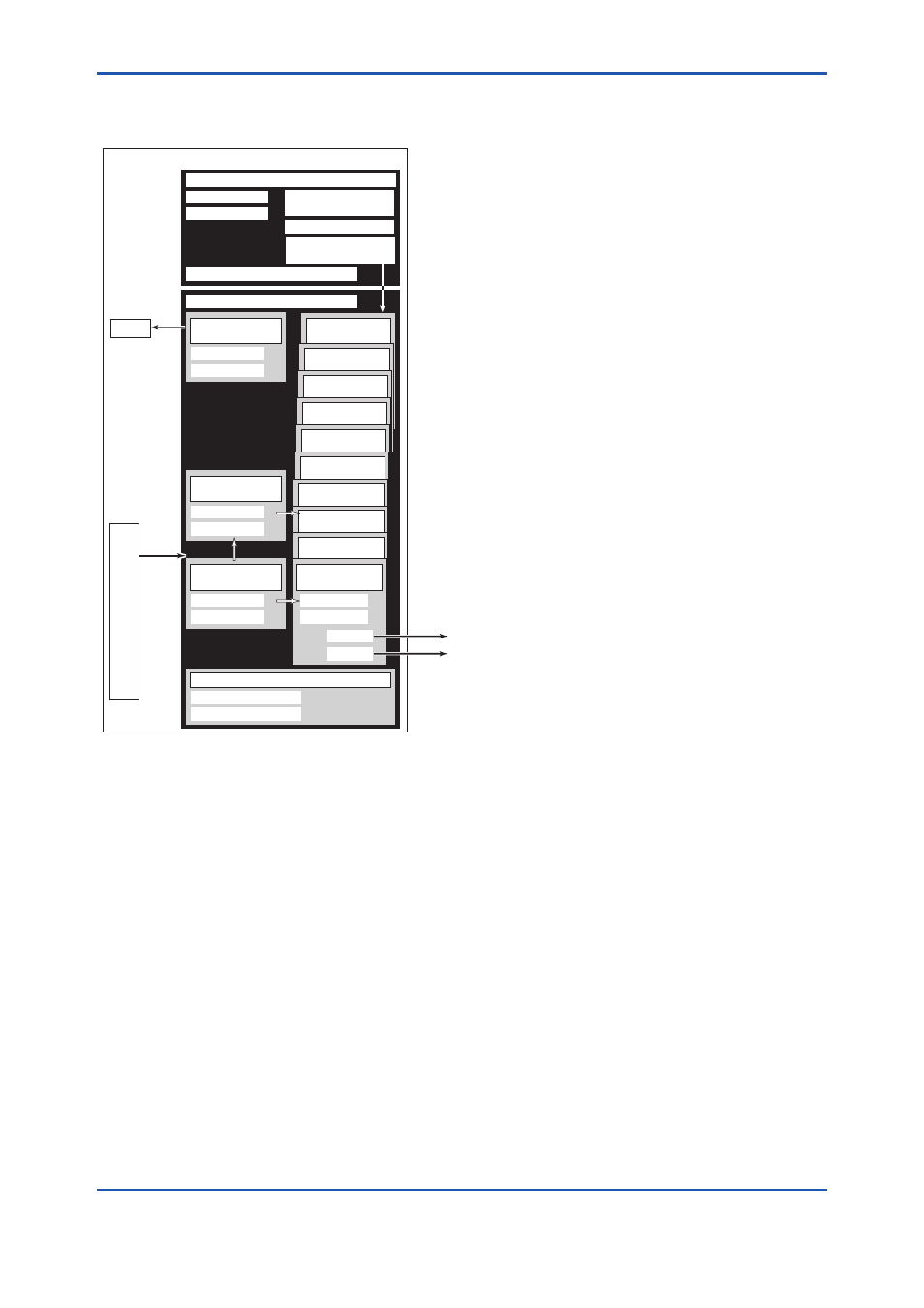
3.3 Logical Structure of Each
Block
PID function
block (option)
F0301.ai
Fieldbus
System/network management VFD
Function block VFD
Link Master
PD Tag
Resource block
Block tag
Parameters
Communication
parameters
VCR
Node address
Function block
execution schedule
LCD
Transducer block
Block tag
Parameters
LCD
AR function
block
IS function
block
IT function
block
SC function
block
AI function
block
AI function
block
AI function
block
AI function
block
Sensor
input
Output
SENSOR
Transducer block
Block tag
Parameters
Flow
Transducer block
Block tag
Parameters
AI function
block
Block tag
OUT
Parameters
OUT_D
Sensor
EJX Multivariable Transmitter
Figure 3.1
Logical Structure of Each Block
Setting of various parameters, node addresses,
and PD Tags shown in Figure 3.1 is required before
starting operation.
3.4 Wiring System Configuration
The number of devices that can be connected to
a single bus and the cable length vary depending
on system design. When constructing systems,
both the basic and overall design must be carefully
considered to achieve optimal performance.