A8-9 – Yokogawa EJX930A User Manual
Page 159
A8-9
IM 01C25R03-01E
Invalid Ref BlkF, fSPh, fSPl, or fDP
This alarm indicates that the reference value under
normal condition is invalid. If REFERENCE_BLKF
is invalid, the blockage detection excluding VALUE_
BLKF is carried out. If blockage detection function
based on VALUE_BLKF is required, obtain the
reference value again.
Also when REFERENCE_DPAVG is below DIAG_
LIM [10] or exceeds DIAG_LIM [9], all reference
value becomes invalid so that “Invalid Ref fDP”,
“Invalid Ref fSPl”, “Invalid Ref fSPh”, and “Invalid
Ref BlkF” are generated.
Alarm Masking
DIAG_OPTION
The alarms linked to an analog alert and LCD
display are selected by DIAG_OPTION in the
SENSOR Transducer block. The BIT of DIAG_
OPTION is corresponding to that of DIAG_ERR.
To link the alarm to an analog alert and LCD display,
follow the procedure below.
1) Set "Stop" to DIAG_MODE.
2) Check each checkbox of the alarm, which is
selectable from bit 2 to bit 14.
Note: The bit 13 and 14 are used for Heat trace monitoring
function.
Set to “Calculation” after setting the parameters.
Analog Alert Setting
Link to DIAG_H_ALM and DIAG_L_ALM
DIAG_H_ALM and DIAG_L_ALM enable to indicate
the alarm status separately divided into the high-
and low-pressure-side alert. The factory setting is
not enabled to display them.
Enable to display the alarm status to DIAG_H_ALM
and DIAG_L_ALM according to the following
procedure.
1) Set "Stop" to DIAG_MODE.
2) Uncheck the checkbox of "Diag Alm Disabled”,
which is corresponding to bit 8, in ALARM_
SUM.
Note: Set to “Calculation” after setting the parameters.
Report Setting
DIAG_PRI in SENSOR Transducer block defines
the priority to transfer the analog alert to the host.
The alert is generated according to the priority when
interfering in other EJX alerts.
DIAG_PRI
Bit
Description
0
An alert is not generated.
1
An alert does not be reported to the host.
2
Disabled
3-7 ADVISORY
8-15 CRITICAL
The default value at the factory setting is set to 1.
Set the priority according to the following procedure.
1) Set "Stop" to DIAG_MODE.
2) Enter the value to DIAG_PRI in the number of 3
to 15.
Note: The setting of the highest priority is 15.
Set to “Calculation” after setting the parameters.
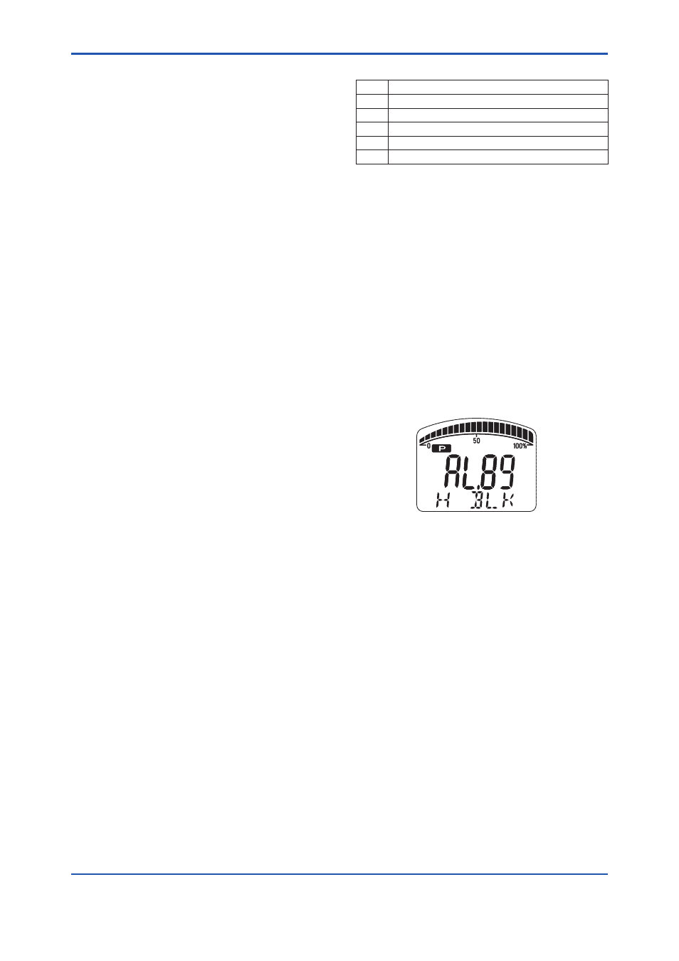
Alarm Display on LCD
If the ILBD algorithm detects the abnormality, the
content of the detected result is displayed with
“AL.88” or “AL.89” on the LCD. “AL.88” indicates
that condition is not applicable for the abnormality
detection and “AL.89” indicates the abnormality is
detected.
FA0808.ai
Figure A8.6 Display Example of High Side Blocking
The alarm display on LCD regarding ILBD is
described in Table 8.12 of the section 8.
Reflect Blockage to PV/SV/TV Status
“Reflect Blockage to PV/SV/TV Status”
corresponding to bit 15 in DIAG_OPTION is
used to link the alarm to the OUT signal status of
PRIMARY_VALUE, SECONDARY_VALUE, and
TERTIARY_VALUE.
When the ILBD algorithm detects the abnormality,
each signal status becomes “UNCERTAIN: Non
Specific”.
The alarm is linked to the signal status of PV, SV
and TV, according to the following procedure.
1) Set "Stop" to DIAG_MODE.
2) Check the checkbox of “Availability for the
Status” of DIAG_OPTION.
Note:Set to “Calculation” after setting the parameters.