Explanation of basic items, 1 outline, 3 sensor transducer block – Yokogawa EJX930A User Manual
Page 40: Explanation of basic items -1, Outline -1, Sensor transducer block -1
<6. Explanation of Basic Items>
6-1
IM 01C25R03-01E
6. Explanation of Basic Items
6.1 Outline
This chapter describes the SENSOR transducer
block, the LCD transducer block, and the AI function
block and explains basic parameter settings.
Refer to Appendixes for other function blocks, LM
function, and software download function.
6.2 Setting and Changing
Parameters for the Whole
Process
IMPORTANT
Do not turn off the power immediately after
setting. When the parameters are saved to the
EEPROM, the redundant processing is executed
for an improvement of reliability. If the power
is turned off within 60 seconds after setting is
made, the modified parameters are not saved
and the settings may return to the original values.
Block mode
Many parameters require a change of the block
mode of the function block to O/S (Out of Service)
when their data is changed. To change the block
mode of the function block, its MODE_BLK needs
to be changed. The MODE_BLK is comprised of
the four sub-parameters below:
(1) Target (Target mode):
Sets the operating condition of the block.
(2) Actual (Actual mode):
Indicates the current operating condition.
(3) Permit (Permitted mode):
Indicates the operating condition that the
block is allowed to take.
(4) Normal (Normal mode):
Indicates the operating condition that the
block will usually take.
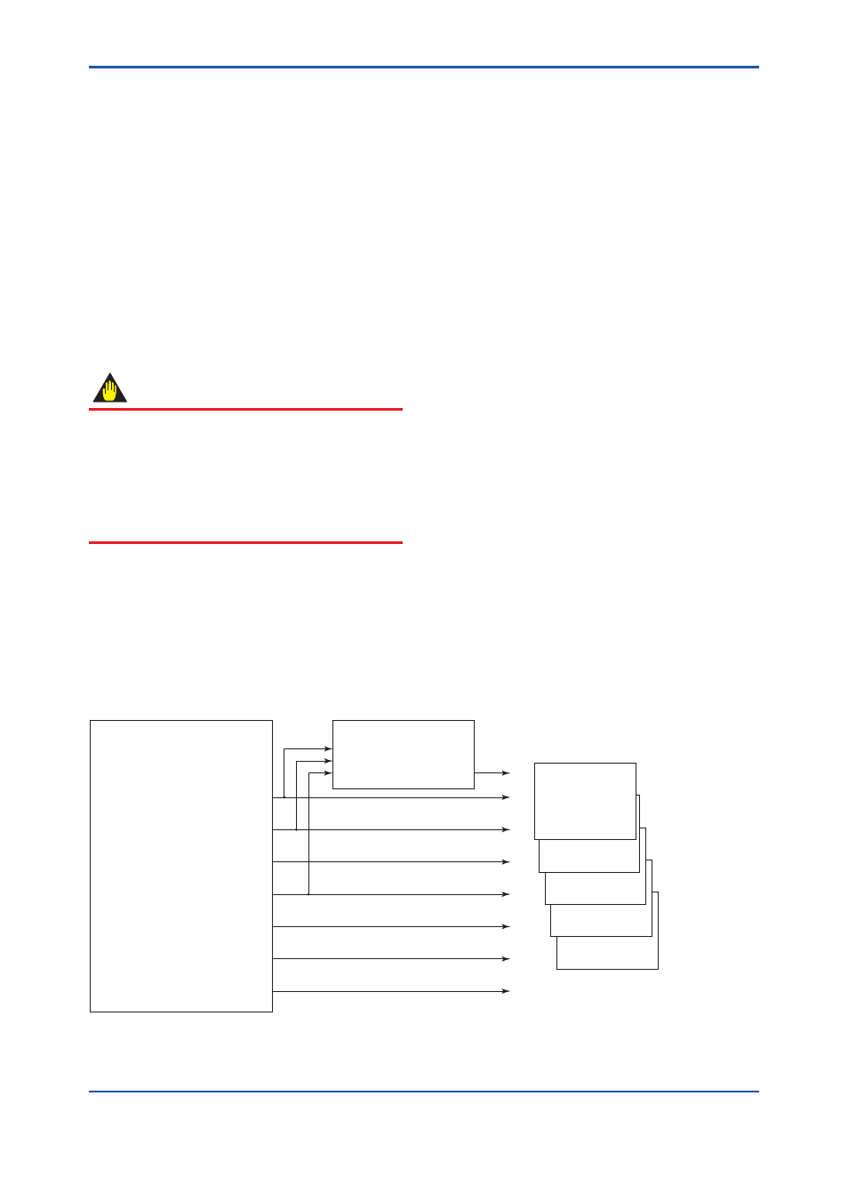
6.3 SENSOR Transducer Block
The SENSOR transducer block is in between the
sensor and the AI function blocks. It calculates
differential pressure, static pressure, external
temperature, and capsule temperature from sensor
signals. Then it performs damping and range
checks for the measured values of these three
variables and sends signals to the AI function block
and Flow transducer block. Figure 6.1 presents the
signal flow between blocks.
F0601.ai
Sensor Transducer Block
PRIMARY_VALUE [DP]
(Channel1)
SECONDARY_VALUE [SP-H]
(Channel2)
TERITARY_VALUE [SP-L]
(Channel3)
EXT_TEMP_VAL
(Channel4)
CAP_TEMP_VAL
(Channel6)
AMP_TEMP_VAL
(Channel7)
FLG_TEMP_VAL
(Channel8)
Flow Transducer Block
FLOW_VAL
(Channel5)
AI Function Block
CHANNEL=?
AI
AI
AI
AI
Figure 6.1
Signal Flow Diagram