Chapter two, Installing, Installers – Watlow Series 96 User Manual
Page 5: Chapter 2: installation, Chapter two installation, Installing the series 96 controller
Chapter Two
Installation
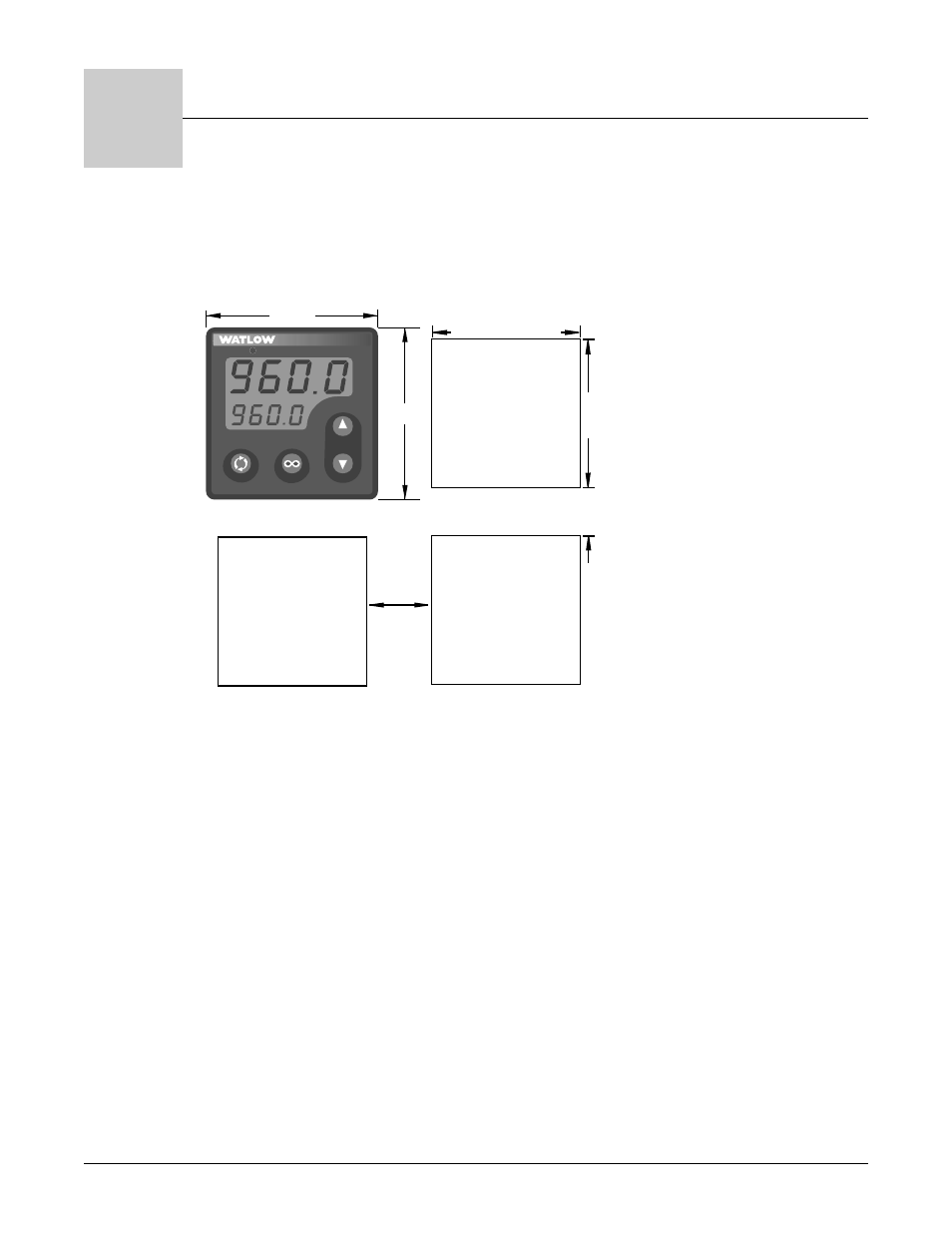
Figure 2.1 – Series 96 multiple panel cutout dimensions.
NOTE: Measurements between panel cutouts are the minimum recommended.
For rapid mounting, use Greenlee 1/16 DIN punch, die, draw stud, part number 60287, available from Grainger.
Installing the Series 96 Controller
Installing and mounting requires access to the back of the panel.
1.
Make the panel cutout using the mounting template dimensions found in this chapter.
2.
Check to see that the gasket is properly seated into the gasket channel on the front
bezel and that it is not twisted. Make sure that the rounded surface of the gasket is the
surface that is exposed from the gasket channel, as this is the surface that will mate to
the panel surface. Insert the controller into the panel cutout.
3.
With the controller inserted into the panel cutout, take the retention collar and slide it
over the controller, making certain that the two locating holes in the retention collar are
visible from the rear of the controller, with one hole pointing up and one pointing down.
Then, take the mounting collar and slide it over the controller, making certain that one
cantilever is pointing up and one is pointing down also. With one hand holding the con-
troller and the other hand using a #2 Phillips screwdriver, tighten the two screws in the
mounting collar until the gap between the bezel and panel surface is .025" maximum.
Panel Cutout
Panel
Thickness
0.06" to 0.38"
(1.5 to 9.7mm)
1.77" to 1.79"
(44.96mm to 45.47mm)
1.77" to 1.79"
(44.96mm
to 45.47mm)
0.540"
(13.72mm)
Minimum
0.310"
(7.874mm)
2
3
4
%
1
2.050"
2.050"
96
Wa t l o w S e r i e s 9 6
I n s t a l l a t i o n
■
2 . 1
2