2 ethernet and usb connectors, Figure 3-20: lan connector, Table 3-15: lan1_usb connector pinouts – IEI Integration KINO-AQ670 User Manual
Page 47
KINO-AQ670
P a g e 33
3.3.2 Eth e rn e t a n d US B Co n n e c to rs
CN La b e l:
LAN1_USB, LAN2_USB
CN Typ e :
RJ-45 , USB 2.0 and USB 3.0 ports
CN Lo c a tio n :
See Figure 3-18
CN P in o u ts :
See Figure 3-20 , Table 3-15 and Table 3-16
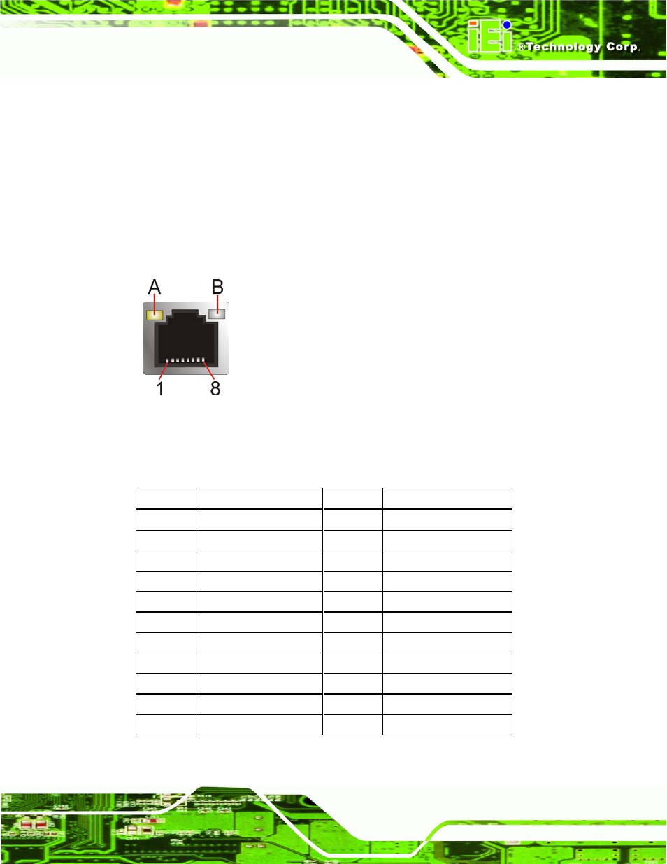
The LAN connector connects to a local network.
Figure 3-20: LAN Connector
The USB 2.0 ports are for attaching USB 2.0 peripheral devices to the system. The
pinouts of LAN1 and USB 2.0 connectors are shown below.
PIN NO.
DESCRIPTION
PIN NO.
DESCRIPTION
P1
+1.9V_LAN1
P2
LAN1_MDIP0
P3
LAN1_MDIN0
P4
LAN1_MDIP1
P5
LAN1_MDIN1
P6
LAN1_MDIP2
P7
LAN1_MDN2
P8
LAN1_MDIP3
P9
LAN1_MDIN3
P10
GND
P11
LAN1_LINK100
P12
LAN1_LINK1000
P13
LAN1_ACT-1
P14
+V3.3A_LAN1
U1
+USB_PWR1
U2
USB20_C_N8
U3
USB20_C_P8
U4
GND
U5
+USB_PWR1
U6
USB20_C_N9
U7
USB20_C_P9
U8
GND
Table 3-15: LAN1_USB Connector Pinouts
- SPCIE-5100DX (180 pages)
- SPCIE-C2060 v1.01 (200 pages)
- SPCIE-C2060 v2.12 (212 pages)
- SPCIE-C2160 (204 pages)
- SPCIE-C2260-i2 (217 pages)
- ROCKY-3786 v4.0 (175 pages)
- ROCKY-3786 v4.10 (147 pages)
- PCIE-Q350 v1.00 (272 pages)
- PCIE-Q350 v1.12 (250 pages)
- PCIE-Q350 v1.20 (250 pages)
- PCIE-Q350 v1.30 (213 pages)
- PCIE-Q57A (159 pages)
- PCIE-G41A2 (151 pages)
- PCIE-Q670 v1.03 (206 pages)
- PCIE-Q670 v2.00 (205 pages)
- PCIE-H610 (181 pages)
- PCIE-Q870-i2 (217 pages)
- IOWA-LX-600 (159 pages)
- PCISA-945GSE v1.01 (207 pages)
- PCISA-945GSE v1.10 (190 pages)
- PCISA-9652 v1.00 (232 pages)
- PCISA-9652 v1.01 (232 pages)
- PCISA-PV-D4251_N4551_D5251 (145 pages)
- PICOe-945GSE (197 pages)
- PICOe-GM45A (198 pages)
- PICOe-PV-D4251_N4551_D5251 v1.00 (154 pages)
- PICOe-PV-D4251_N4551_D5251 v1.10 (154 pages)
- PICOe-PV-D4251_N4551_D5251 v1.11 (155 pages)
- PICOe-B650 (156 pages)
- PICOe-HM650 (174 pages)
- HYPER-KBN (139 pages)
- SPXE-14S (3 pages)
- SPXE-9S v1.00 (5 pages)
- SPXE-9S v1.1 (6 pages)
- SPE-9S v1.00 (4 pages)
- SPE-9S v1.1 (5 pages)
- SPE-6S (3 pages)
- SPE-4S (4 pages)
- PE-6SD3 (4 pages)
- PE-6SD2 v4.0 (4 pages)
- PE-6SD2 v2.10 (3 pages)
- PE-6SD (3 pages)
- PE-6S3 v1.0 (2 pages)
- PE-6S3 v4.0 (4 pages)
- PE-6S2 (4 pages)