Ia net – IAI America XSEL-S User Manual
Page 53
Chapter 3 Operation (Construction for Network)
47
IA Net
XSEL-R/S
3.2.2 Settings for Extension I/O Unit Connection
To an extension I/O unit, four I/O boards at the maximum can be mounted.
There are three types of I/O boards available with different number of input and output points.
[Refer to the instruction manual of XSEL-R/S for the details.]
Set the following parameters demonstrated in steps 1 through 3.
[Setting 1: Selection of Slot to Use]
No.
Parameter name
(I/O parameters)
Initial Value
(Reference) Input Range
Remarks
705 Extension I/O Unit Use Select
0
H
0 to
FFFFFFFF
H
Bits 0 to 3 : Select Slot 1 Usage
Bits 4 to 7 : Select Slot 2 Usage
Bits 8 to 11 : Select Slot 3 Usage
Bits 12 to 15 : Select Slot 4 Usage
Set Value: (0 : Unused,
1 : Only output to be used,
2 : Only input to be used,
3 : Input and output to be used)
In I/O Parameter No.705 “Extension I/O Unit Use Select”, set whether to use or not to use each
slot.
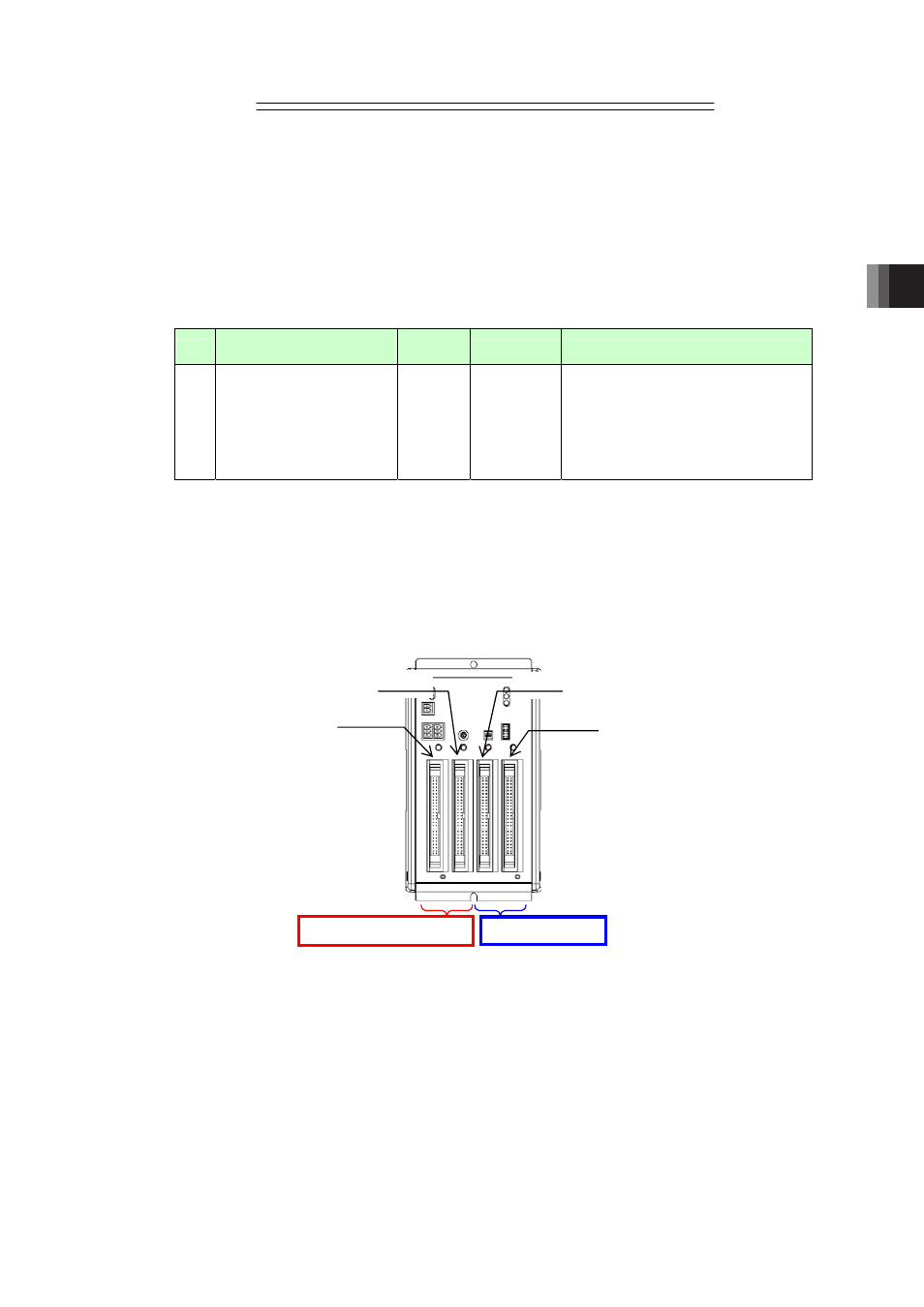
(Example) Case that the input and output in Slot 1 and Slot 2 are used, but Slot 3 and Slot 4
are not used
� Set I/O Parameter No.705 = 0033
H
Note 1 A PIO board mounted in an Extension Unit I/O slot occupies 1 station. Output boards
can not be shared among multiple XSEL controllers.
Note 2 Input boards can be shared among multiple XSEL controllers.
Note 3 The total number of I/O points on an extension I/O unit is determined by the type and
number of mounted PIO boards.
Input and output used
Unused
Slot 1
Slot 2
Slot 3
Slot 4