Chapter 2 wiring, Ia net, Xsel-r/s – IAI America XSEL-S User Manual
Page 31
Chapter 2 Wiring
25
IA Net
XSEL-R/S
Chapter 2 Wiring
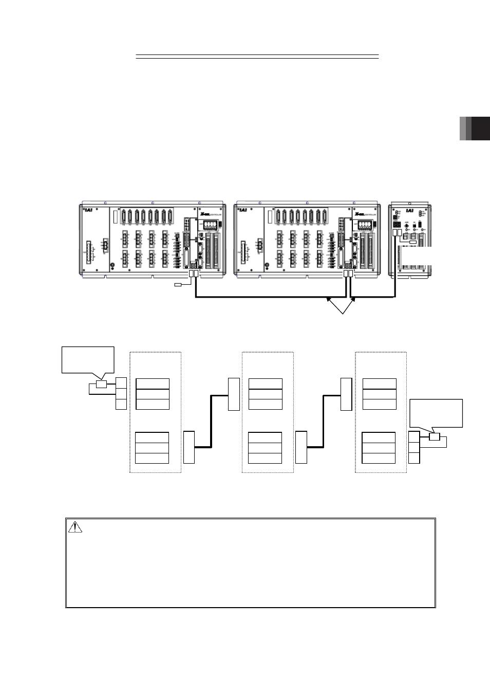
The wiring between each of XSEL controllers and extension I/O units should be accomplished
exclusively with dedicated IAI original equipment cables.
Connect terminal resistors on both ends of the network.
The maximum number of connectable units (total of XSEL controllers and extension I/O units)
differs depending on the construction. Establish the network construction in advance and check
the number of connectable units. Refer to Section 3. Operation for details.
Note 1 * * * : Cable length
Caution
Simultaneous power application to XSEL controllers connected to the IA Net is recommended.
When booting an IA Net connected XSEL controller, the system waits for the link of all the
stations set in I/O Parameters No.605 and 606. In case the link of all the stations is not
confirmed, “211/552: IA Net Link Error” will be issued.
Link Establish Waiting Time can be adjusted in Bit 24 to 31: IA Net Initializing Link Waiting
Timeout (sec) in I/O Parameter No. 608 “IA Net Attribute 1” (Initial setting = 15sec). Adjust the
time if necessary.
Dedicated
cable
for IA Net
(CB-RS-IAN
* * *
(Note 1)
)
FMC1.5/3-ST-3.5
(PHOENIX
CONTACT)
FMC1.5/3-ST-3.5
(PHOENIX
CONTACT)
IA Net
Connector 1
IA Net
Connector 2
XSEL Controller 1st Unit
1(SA)
2(SB)
3(SLD)
1(SA)
2(SB)
3(SLD)
IA Net
Connector 1
IA Net
Connector 2
XSEL Controller 2nd Unit
1(SA)
2(SB)
3(SLD)
1(SA)
2(SB)
3(SLD)
IA Net
Connector 1
IA Net
Connector 2
Extension I/O Unit
1(SA)
2(SB)
3(SLD)
1(SA)
2(SB)
3(SLD)
Terminal
Resistance
R=100:1/2W
䎃
Terminal
Resistance
R=100:1/2W
XSEL Controller 1st Unit
XSEL Controller 2nd Unit
Extension
I/O Unit
Terminal
Resistance
Terminal
Resistance
CB-RS-IAN * * *
(Note 1)
Dedicated
cable
for IA Net
(CB-RS-IAN
* * *
(Note 1)
)