Ia net – IAI America XSEL-S User Manual
Page 38
Chapter 3 Operation (Construction for Network)
32
IA Net
XSEL-R/S
3.1.4 Functions of IA Net
IA Net possesses three communication functions.
(1) I/O communication among XSEL controllers
(2) I/O communication of extension I/O unit
(3) Connection of PC software with XSEL controllers
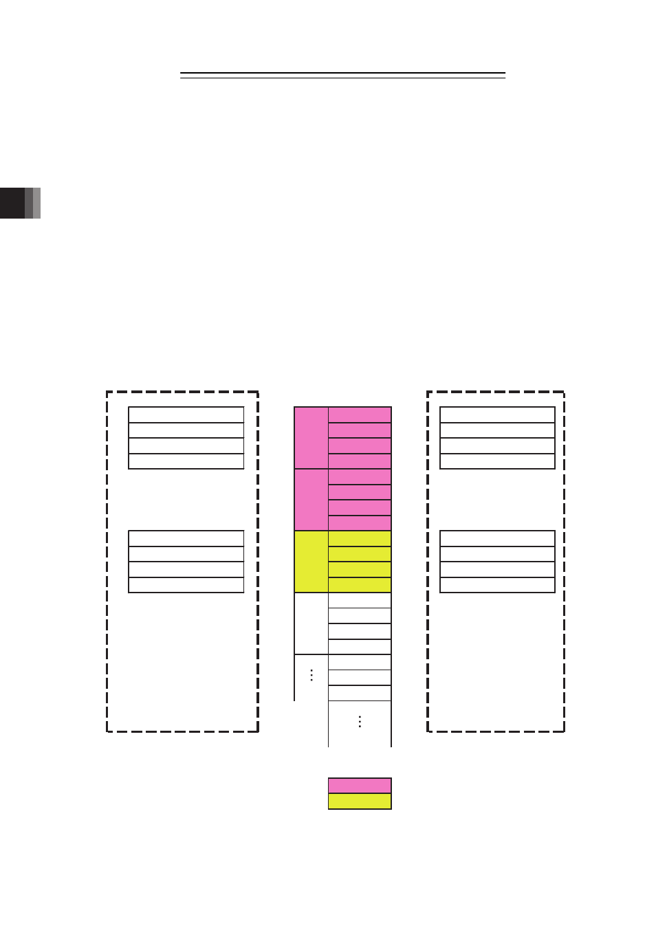
[1] Guideline of I/O Communication among XSEL Controllers
The diagram below shows the flow of PIO signals between two units of XSEL
The condition of the extension output port that is turned ON/OFF on X-SEL1 can be written
from the extension input port on X-SEL2 via the shared memory. At the same time, the
condition of the extension output port that is turned on/off on X-SEL2 can be written from the
extension input port on X-SEL1.
X-SEL can turn ON/OFF from the extension output port only on the stations that it occupies.
The stations other than what are occupied cannot be turned ON/OFF. The condition of ON/OFF
can be referred (read) from all the XSEL controllers connected to the IA Net network.
4015 to 4000 → No.0 → 1015 to 1000
4031 to 4016 → No.1 → 1031 to 1016
4047 to 4032 → No.2 → 1047 to 1032
4063 to 4048 → No.3 → 1063 to 1048
No.4
No.5
No.6
No.7
1015 to 1000 ← No.8 ← 4015 to 4000
1031 to 1016 ← No.9 ← 4031 to 4016
1047 to 1032 ← No.10 ← 4047 to 4032
1063 to 1048 ← No.11 ← 4063 to 4048
No.12
No.13
No.14
No.15
No.16
No.17
No.18
Occupied stations for X-SEL 1
Occupied stations for X-SEL 2
St.
No.0
St.
No.1
St.
No.2
St.
No.3
Extension Input Port No.
Extension Input Port No.
Extension Output Port No.
X-SEL 1
Top Station
No.0
X-SEL 2
Top Station
No.2
IA Net
Shared Memory
Extension Output Port No.