Ia net – IAI America XSEL-S User Manual
Page 43
Chapter 3 Operation (Construction for Network)
37
IA Net
XSEL-R/S
Continued from previous page
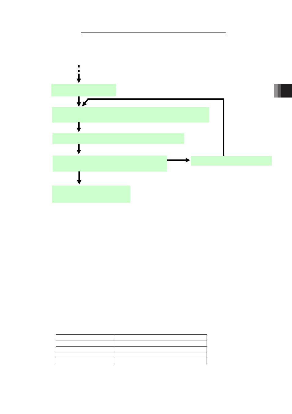
The following steps explain the basic flow to create the assignment table.
(4) Assign
(Note 2) (Note 4)
the number of output points (256 points at max.) except for those on
extension I/O units in 1
st
unit of XSEL to the shared memory (output side). Assign the
numbers in a raw from the top shared word number of each station.
(5) Assign
(Note 2) (Note 4)
the number of output points on extension I/O units occupied by one unit of
XSEL to the shared memory (output side). Even if there is a shared word domain that is not
assigned at that time, do not assign to a station that is already assigned in (4) and assign to
the next station. Also, when occupying multiple slots, assign to slots one by one.
(6) Make the total of the number of the stations assigned in (4) and (5) four or less
(Note 3)
.
(7) Conduct steps (4) to (6) also to the rest of the XSEL units. Have the settings done from the
station number after those used for the XSEL unit set one before.
(8) Reserve four stations in a raw that are occupied by extension I/O unit with a consideration
that the top station number is a multiple of 4 (4n).
In case several extension I/O units are to be connected, reserve four stations in the same
way for each unit. The reserved four stations apply for Input port of each slot on each
extension I/O unit. [Refer to the table below.]
Station No.
Slot Number of Extension I/O Unit Slot
4n (Multiples of 4)
1
4n+1
2
4n+2
3
4n+3
4
XSEL Unit Number = No. 1
Assignment table completed
Establish the parameter settings
Is assignment of inputs on all the connected XSEL
units completed?
XSEL Unit Number = Next Number
Assign the input ports on the occupied extension I/O units
Assign input ports (those on occupied extension I/O units excluded) to
domain of shared memory to be read
Yes
No