IAI America IX-NNN1805 User Manual
Page 73
67
12. Precautions for Use
IX-NNC1205/1505/1805
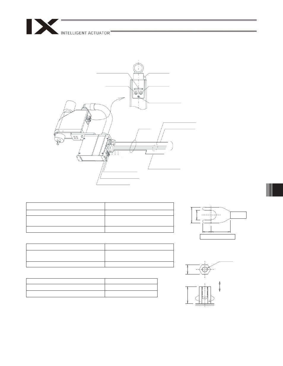
User connector specifications
Shape of Y-terminal
Rated voltage
30 V
Permissible current
1.1 A
Conductor size and number of wires
AWG 26 (0.15 mm
2
), 8 wires
(U1 to U8)
Other Shielded
Piping specifications
Normal service pressure
0.7 MPa
Dimensions (outer diameter x inner
diameter) and number of tubes
3 mm x 2 mm, 2 pieces
Working medium
Air
ALM (indicator) specifications
Rated voltage
24 VDC
Rated current
12 mA
Illumination color
Red LED
Quick joint
3,
white
Quick joint
3,
black
ALM (indicator)
User connector
8-pin
SM P-08V-NC
J.S.T. Mfg. Co., Ltd.
User spacer (FG)
M3, depth 6
Standard
3 m
To controller
Terminal: Y terminal
Quick joint
6, (for suction)
Quick joint
3, white
U cable (outside robot)
PG cable (outside robot)
M cable (outside robot)
Quick joint
3, black
To air tube provided
by the user
5.
2
5.
5
10
3.
2
2.6
5.9
Y
Spacer for user part installation
M3, depth 6
10 N
m or less
0.81 N
m or less
Torques shall not be
added in the direction
where spacers get loose.
Shape of Y-terminal