2 machine harness wiring table – IAI America IX-NNN1805 User Manual
Page 37
31
4. W
iring Diagram
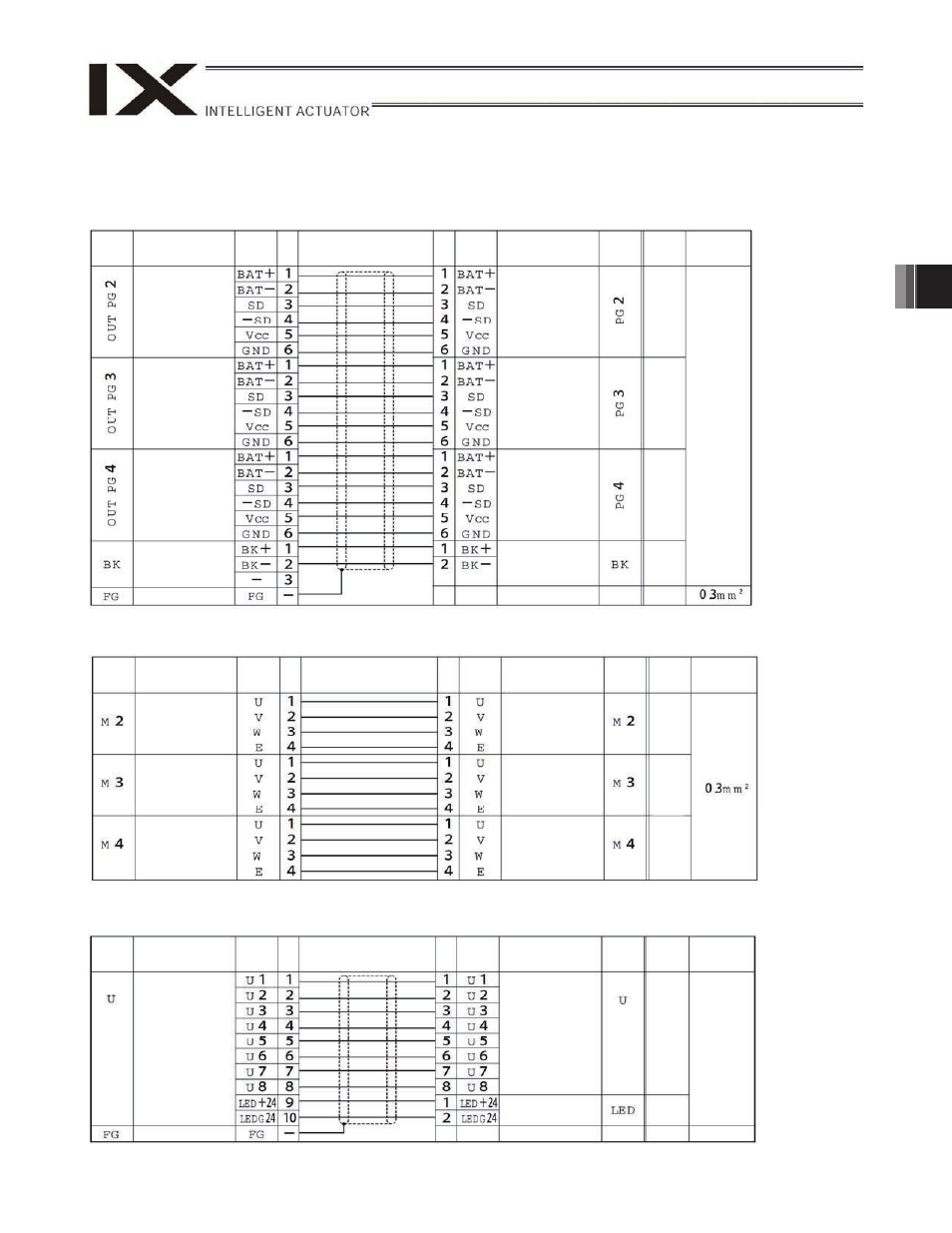
4.2 Machine Harness Wiring Table
(1) PG cables (inside robot)
DWG No. 1090996*
Base end
Arm 2 end
(2) M cables (inside robot)
DWG No. 1090998*
Base end
Arm 2 end
(3) U cables (inside robot)
DWG No. 1090997*
Base end
Arm 2 end
Red
White
Black
Green
Red
White
Black
Green
Red
White
Black
Green
Socket
DF3-4S2C
(Hirose)
Tube
symbol
Connector
Signal
Pin
No.
Connection
ID No.
Cable
Pin
No.
Connector
Signal
Tube
symbol
Relay plug
DF11-4EP-2C
(Hirose)
Same as above
Same as above
Same as above
Same as above
Black
Black
Plug housing
SMP-08V-NC
(JST)
Receptacle
housing
SM R-10V-N
(JST)
0.3-mm
2
10-core
shielded
cable
Socket
DF3-2S-2C
(Hirose)
Tube
symbol
Connector
Signal
Pin
No.
Connection
ID No.
Cable
Pin
No.
Connector
Signal
Tube
symbol
Tube
symbol
Connector
Signal
Pin
No.
Connection
ID No.
Cable
Relay plug
DF11-6DEP-2C
(Hirose)
Socket
DF11-6DS-2C
(Hirose)
Same as above
0.3-mm
2
twisted-
pair, 20-
core
shielded
cable
Pin
No.
Connector
Signal
Tube
symbol
Same as above
Same as above
Same as above
Relay plug
DF3-2EP-2C
(Hirose)
Red
Red
Red
Red
Relay plug
DF3-3EP-2C
(Hirose)
Round terminal
Round terminal