IAI America IX-NNN1805 User Manual
Page 28
22
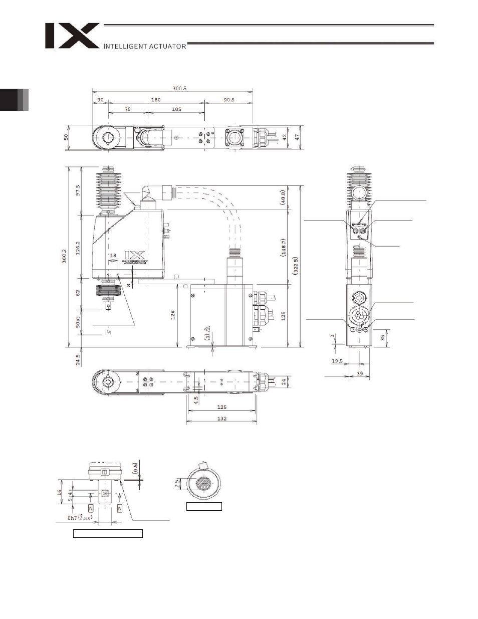
2. External Dimensions
IX-NNC-1805 (arm length 180, clean room specification)
Detail view of arm end (1/1)
ALM lamp
(Note 2)
2-M3, depth 6
Same on opposite
side (Note 1)
User connector
8-pin
SM P-08V-NC
J.S.T. Mfg. Co., Ltd.
Quick joint
3,
black
Quick joint
3,
white
Quick joint
3,
black
M3, depth 6
Quick joint
3,
white
Section A-A
Note 1: These holes are plugged with setscrews. Also, the holes
denoted by “2-M3, depth 6” are through holes connecting both
sides of the arm. Take note that long mounting screws may
contact the internal mechanism parts.
Note 2: The ALM lamp will turn on when the user wires the applicable
lines in such a way that 24 VDC is applied to the user-wired
LED terminal upon I/O output of a signal from the controller.
Note 3: The vertical axis has no brake. Accordingly, be careful when a
load corresponding to the maximum loading capacity is
installed because the vertical axis may drop once the servo
turns off.
Note 4: The cleaning performance is demonstrated when air inside the
robot is suctioned from the suction joint to create vacuum.
(Take note that dust will be raised if suction is not provided.)
Quick suction
joint
6
Reference
surface
Provide a clearance
of approx. 0.5 mm
when installing the
tool.