28 4. w iring diagram – IAI America IX-NNN1805 User Manual
Page 34
28
4. W
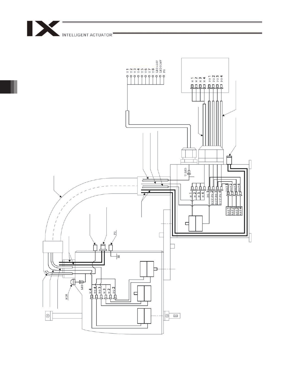
iring Diagram
PG ca
ble (
inside
r
o
bo
t)
M cable (insid
e rob
o
t)
U cable (insid
e rob
o
t)
Flex
ible cable
U cable (insid
e rob
o
t)
M cable (insid
e rob
o
t)
PG ca
ble (
inside
r
obo
t)
User conn
ector
U cable (o
utside
rob
o
t)
User w
iring
terminals
Co
n
tro
lle
r
M cable (o
utside
robo
t)
PG ca
ble (
o
u
tside r
o
bo
t)
4
-ax
is
e
n
code
r
4-
ax
is
mot
or
3-
ax
is
mot
or
3
-ax
is
e
n
code
r
2
-ax
is
en
co
d
e
r
2-
ax
is
mot
or
Ai
r tubes
1
-ax
is
en
co
d
e
r
1-
ax
is
mot
or
Air joint
Wh
it
e
(
3),
Black (
3)
Ai
r tubes
Air joint
Wh
it
e
(
3),
Black (
3)
FG (f
ram
e
)
This manual is related to the following products: