29 4. w iring diagram – IAI America IX-NNN1805 User Manual
Page 35
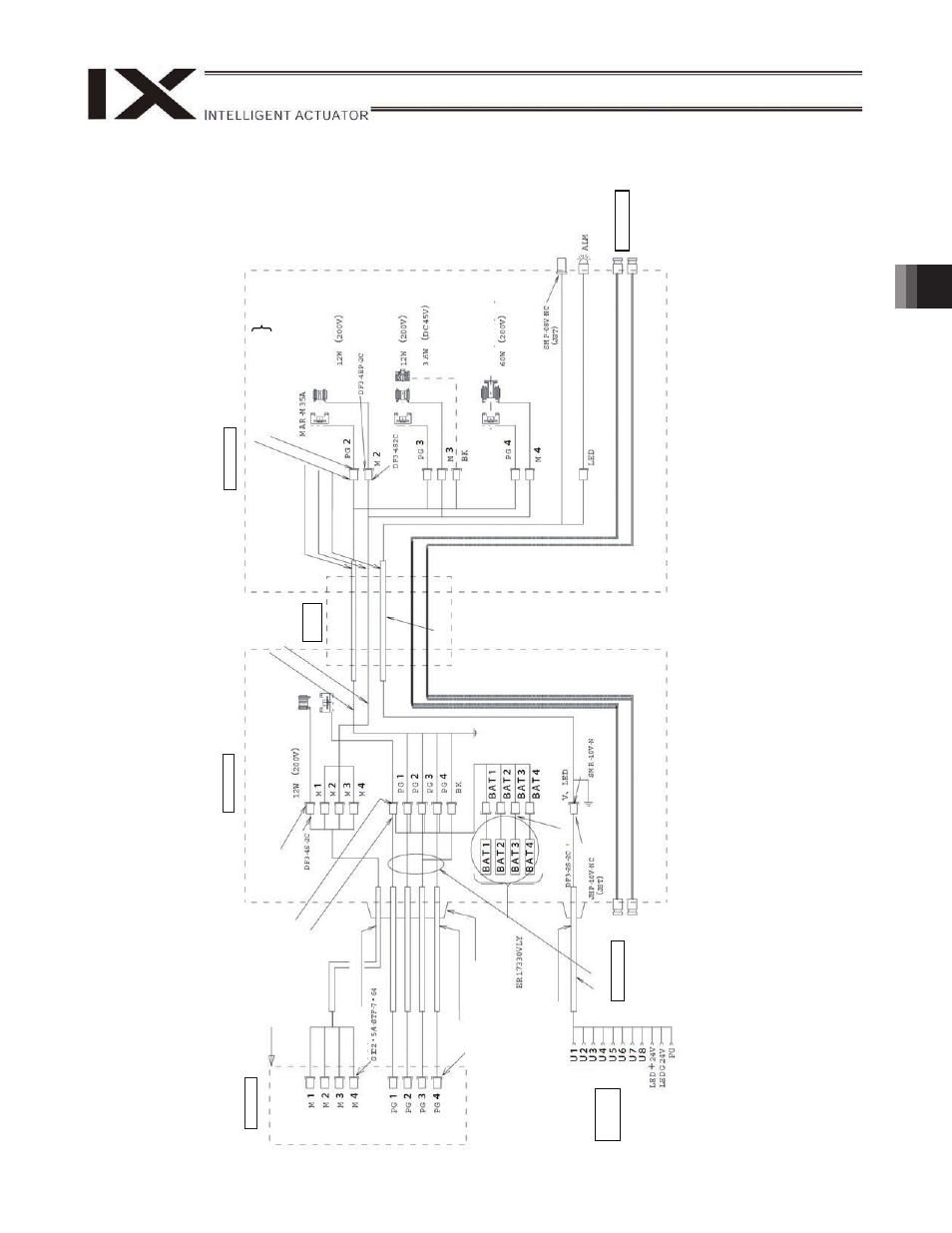
29
4. W
iring Diagram
Notes
(1)
To opera
te
the
alar
m LED, the
u
s
er
m
ust prov
ide a
ci
rcui
t
that u
s
e
s
the
con
tr
oller
I/O ou
tpu
t
sign
al.
(2)
If 24
VDC i
s
no
t su
pplied
to
the
bra
ke
pow
er-supply
conne
ctor on
the
controlle
r, th
e bra
ke
canno
t b
e
rel
eased
.
IX-NNC1205/1505/1805
Co
n
tro
lle
r
Inside
bas
e
Insi
de ar
m 2
D
W
G
No. 10909
96*
D
W
G
No. 10909
98*
F
lex
ib
le
c
able
PG
c
abl
e (
ins
ide
r
obot)
M c
abl
e (
ins
ide
r
obot)
U c
abl
e (
ins
ide r
o
bot)
D
W
G
No. 10909
971
(P
hoe
nix
c
on
tac
t)
Plu
g-
in
c
onn
ec
tor
1012
6-
30
00V
E
(S
um
itom
o 3M)
Rela
y
plu
g
DF1
1-6D
EP-2C
Soc
k
et
DF
11-
6D
S-
2S
(Hi
ro
s
e
)
Rela
y
plu
g
DF3-4E
P-2C
Ax
is
1 (arm
1)
rotor/stator
AB
S e
n
c
oder
M c
abl
e (
ou
ts
ide
r
obot)
PG
c
abl
e (
ou
ts
ide
r
obot)
Cap (
C
a
pc
on)
Dedic
a
ted
batt
er
ies
f
or
IX
1
20/1
50
U
s
er
w
ir
ing
term
in
al
U
s
er
pi
pi
ng
D
W
G
No. 10909
85*
U c
abl
e (
outs
ide r
o
bot)
A
ir jo
in
t,
wh
it
e
(
3)
A
ir jo
in
t,
b
la
ck
(
3)
Soc
k
et
Plu
g h
ous
in
g
FG (to f
ra
m
e)
Rec
eptac
le h
ous
ing
(JS
T
)
FG (to frame)
D
W
G
No. 10909
97*
Soc
k
et
DF
11-
6D
S-
2C
Rela
y
pl
ug
DF
11-
6D
EP-
2C
AB
S e
n
c
oder
Hi
rose
Ax
is
3 (
v
er
tic
a
l ax
is
)
rotor
/s
tator
Br
ak
e [opti
ona
l]
Ax
is
4 (rota
tio
na
l ax
is
)
rotor/stator
Conn
ec
tor
f
or
us
er
wir
ing:
SM
P-
08
V-
NC
(J
ST
, 8 -
pi
n)
User
c
onnec
tor
P
lug
ho
u
s
ing
A
lar
m
LED
A
ir jo
in
t,
wh
it
e
(
3)
A
ir jo
in
t,
b
la
ck
(
3)
Soc
k
et
(H
ir
os
e)
Ax
is
2 (arm
2)
rotor
/s
tator
U
s
er
pi
pi
ng
If
ar
m
3 has
a br
ak
e,
the c
ontr
ol
ler
m
us
t als
o
hav
e a
br
ak
e unit.
Plu
g
If
ar
m
3 has
a br
ak
e, s
upp
ly
24 V
DC to
the
brak
e po
w
e
r-
s
uppl
y
c
on
nec
tor
o
n th
e
c
ontr
ol
ler
.