IAI America IX-NNN1805 User Manual
Page 63
57
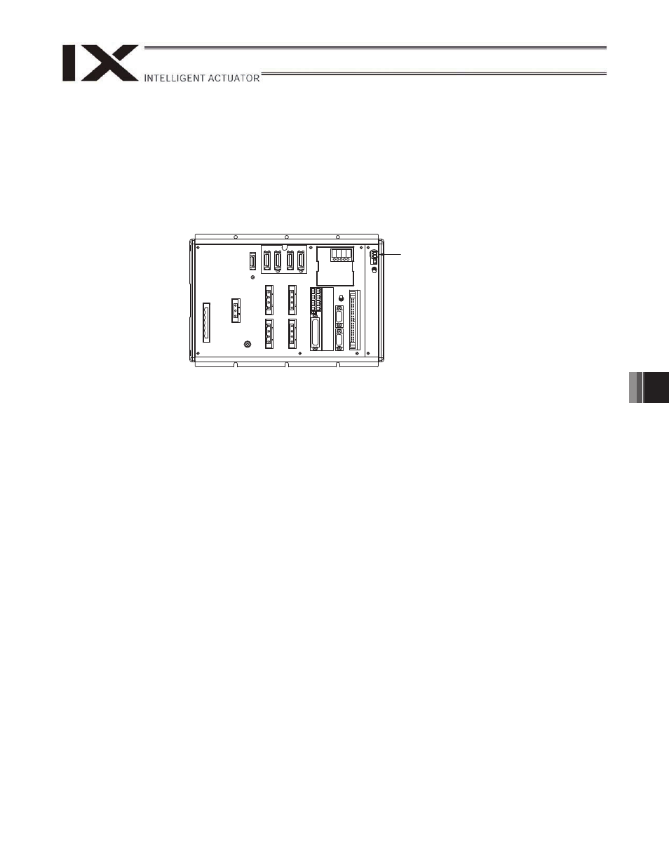
10. Connecting the Controller
x Connect the cables securely after confirming that they are free from damage or bent connector pins.
x Connect each cable by aligning the indication on the marking tube on the cable with the indication on the
controller panel.
x When installing the PG connector (D-sub connector), ensure correct orientation of the connector.
x In the case of a controller with brake, provide a dedicated DC power supply for the brake. Do not use the I/O
power supply or power supply for secondary circuit.
This power supply must have an output voltage of 24 VDC
r 10% and capacity of approx. 5 W.
Refer to the operation manuals for the controller and PC software for the procedures to connect the I/O cable,
controller power cable, PC connection cable, etc.
24-VDC power-supply input
Controller (without brake)