External dimensions, 17 2. external dimensions – IAI America IX-NNN1805 User Manual
Page 23
17
2. External Dimensions
Reference surface
Reference surface
15
8h7(
-0.015
)
0
2. External
Dimensions
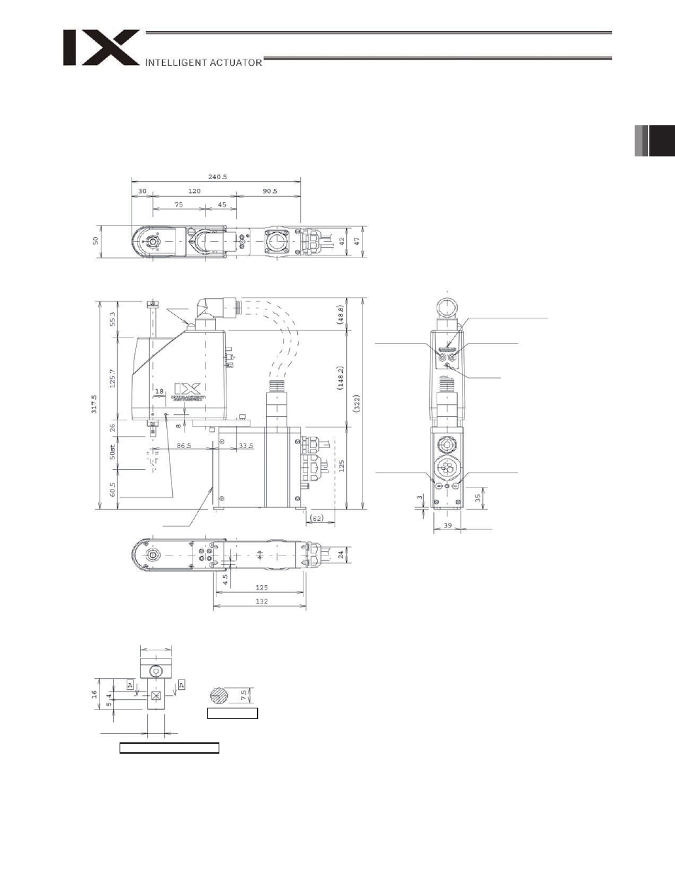
IX-NNN-1205 (Arm Length 120, Standard Specification)
Detail view of arm end (1/1)
ALM lamp
(Note 2)
2-M3, depth 6
Same on opposite
side (Note 1)
Cable wiring space
User connector
8-pin
SM P-08V-NC
J.S.T. Mfg. Co., Ltd.
Quick joint
3,
black
Quick joint
3,
white
Quick joint
3,
black
FG
M3, depth 6
Quick joint
3,
white
Section A-A
Note 1: The holes denoted by “2-M3, depth 6” are through holes
connecting both sides of the arm. Take note that long mounting
screws may contact the internal mechanism parts.
Note 2: The ALM lamp will turn on when the user wires the applicable lines
in such a way that 24 VDC is applied to the user-wired LED
terminal upon I/O output of a signal from the controller.
Note 3: The vertical axis has no brake. Accordingly, be careful when a load
corresponding to the maximum loading capacity is installed
because the vertical axis may drop once the servo turns off.