IAI America RCS2-A6R User Manual
Page 51
4. Maintenance Inspection
45
[Procedure]
(1) Remove the pulley cover using Allen wrenches, 2.5 mm across flats.
�
�
�
�
�
�
�
�
�
�
�
�
�
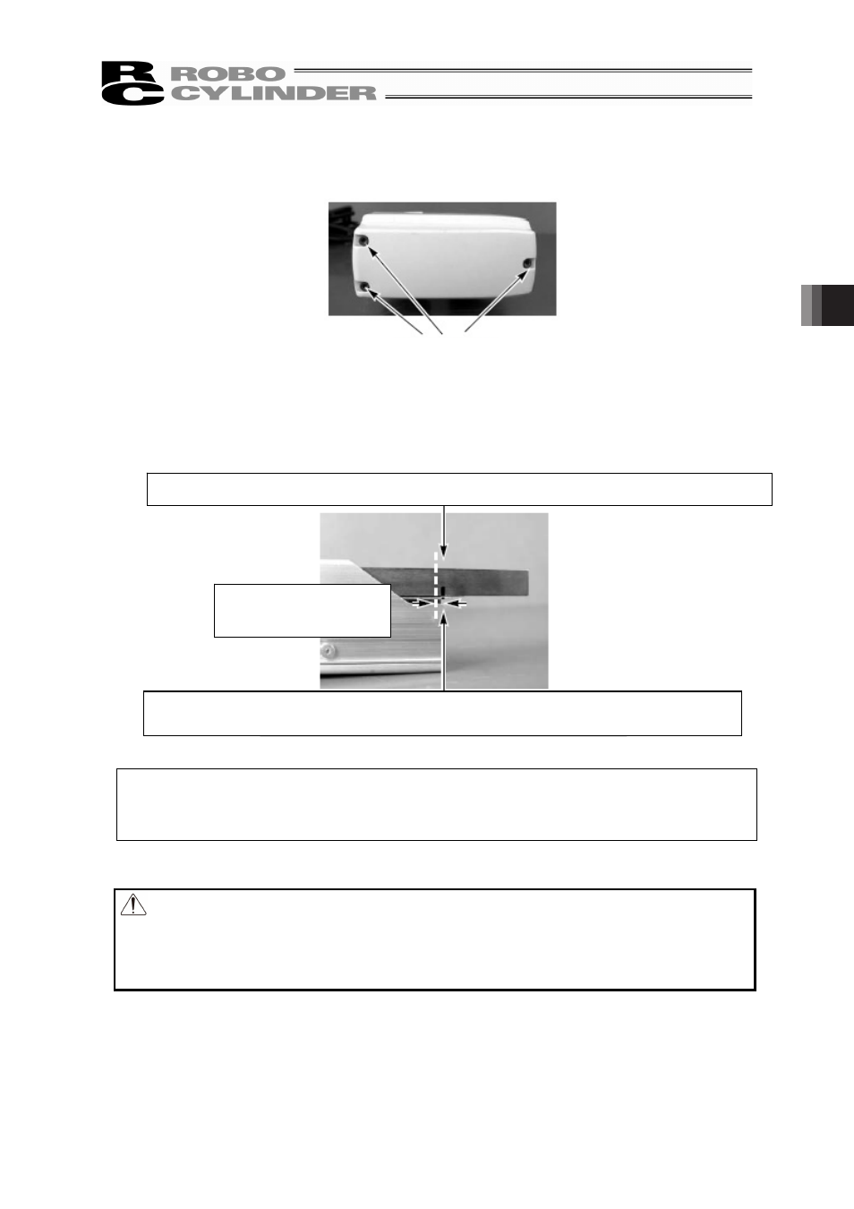
(2) Move the slider to a position where Z phase turns ON (home position).
This corresponds to a position where the rod projects A4R is 0.6mm, A5R and A6R is 0.7mm
from the mechanical end.
Apply countermarks in this position.
�
�
�
�
If the actuator has a brake, connect this machine to the controller and pull out the slider to the
stroke end after the brake has been released with the brake release switch. Then, turn OFF
the controller power for safety.
�
�
�
Warning: If the actuator is installed vertically, move it after turning on the controller
power and forcibly releasing the brake. At this time, beware of danger as the
actuator may drop suddenly.
Always provide a support to brace the actuator hand to prevent sudden drop,
so as not to pinch fingers or damage the load.
�
�
�
M3 hexagon socket head screws
Cause the
slider to project A4R is 0.6mm, A5R and A6R is 0.7mm from the mechanical end.
Apply countermarks once the
slider has projected A4R is 0.6mm, A5R and A6R is 0.7mm
from the mechanical end.
A4R
:
0.6mm
A5R and A6R
:
0.7mm