Dcp mode 3 for a 5ess switch, Figure 6-4. dcp mode 3 network for a 5ess switch – AT&T AUDIX Networking 585-300-903 User Manual
Page 73
DCP Mode 3 Networks — 64 Kbps
6-7
_
______________________________________________________________________________________
_
______________________________________________________________________________________
_
______________________________________________________________________________________
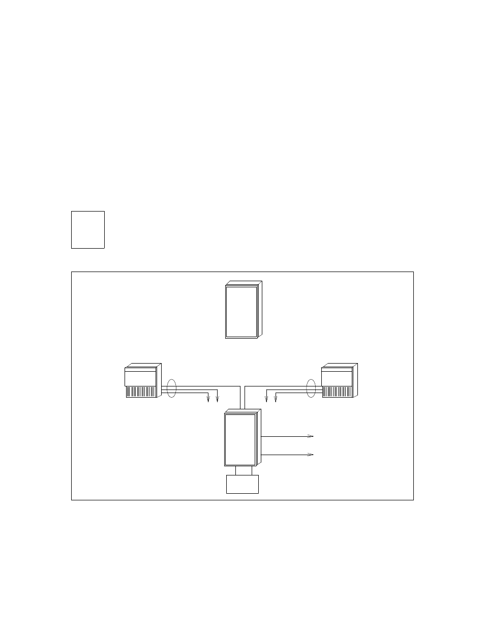
DCP MODE 3 FOR A 5ESS SWITCH
Figure 6-4, DCP Mode 3 Network for a 5ESS Switch, shows how a Generic 2 provides the DCP and DS1
interfaces for a 5ESS Centrex switch (an example of a non-DCP switch). The customer has installed the
AUDIX system to serve their employees which reside on the Centrex. A ‘‘bare-bones’’ Generic 2 is
installed for its DCP, DS1, modem pooling, and alternate routing capabilities only. No stations reside on
the Generic 2. The Generic 2 does the following:
•
Provides a 64 Kbps digital network path between the two AUDIX systems shown.
•
Provides a 64 Kbps digital network path to an AUDIX system located outside the 5ESS environment.
•
Generic 2 software (R2V5) provides the ability to designate the digital path as the first-choice facility
with the analog path providing backup (see the Automatic Alternate Routing feature).
NOTE
Any network of this nature is considered experimental and should be developed on an
individual basis by the BCSDC.
MODEM
POOL
. . .
. . .
. . .
. . .
. . .
. . .
. . .
. . .
. . .
.
. .
. .
. .
. .
. .
. .
. .
. .
. .
. .
. .
. .
. .
. .
. .
.
AUDIX
AUDIX
DCP
DCP
5ESS
AT&T
FOR REMOTE
NETWORKING
T/R
DS1
H600-331
GROUP 2
RS-232
(NOT
USED)
RS-232
(NOT
USED)
H600-331
GROUP 2
CONTROL LINK
VOICE PORTS
ALARM LINK
CONTROL LINK
VOICE PORTS
ALARM LINK
G2
Figure 6-4. DCP Mode 3 Network for a 5ESS Switch