Figure 3-3 – AT&T AUDIX Networking 585-300-903 User Manual
Page 43
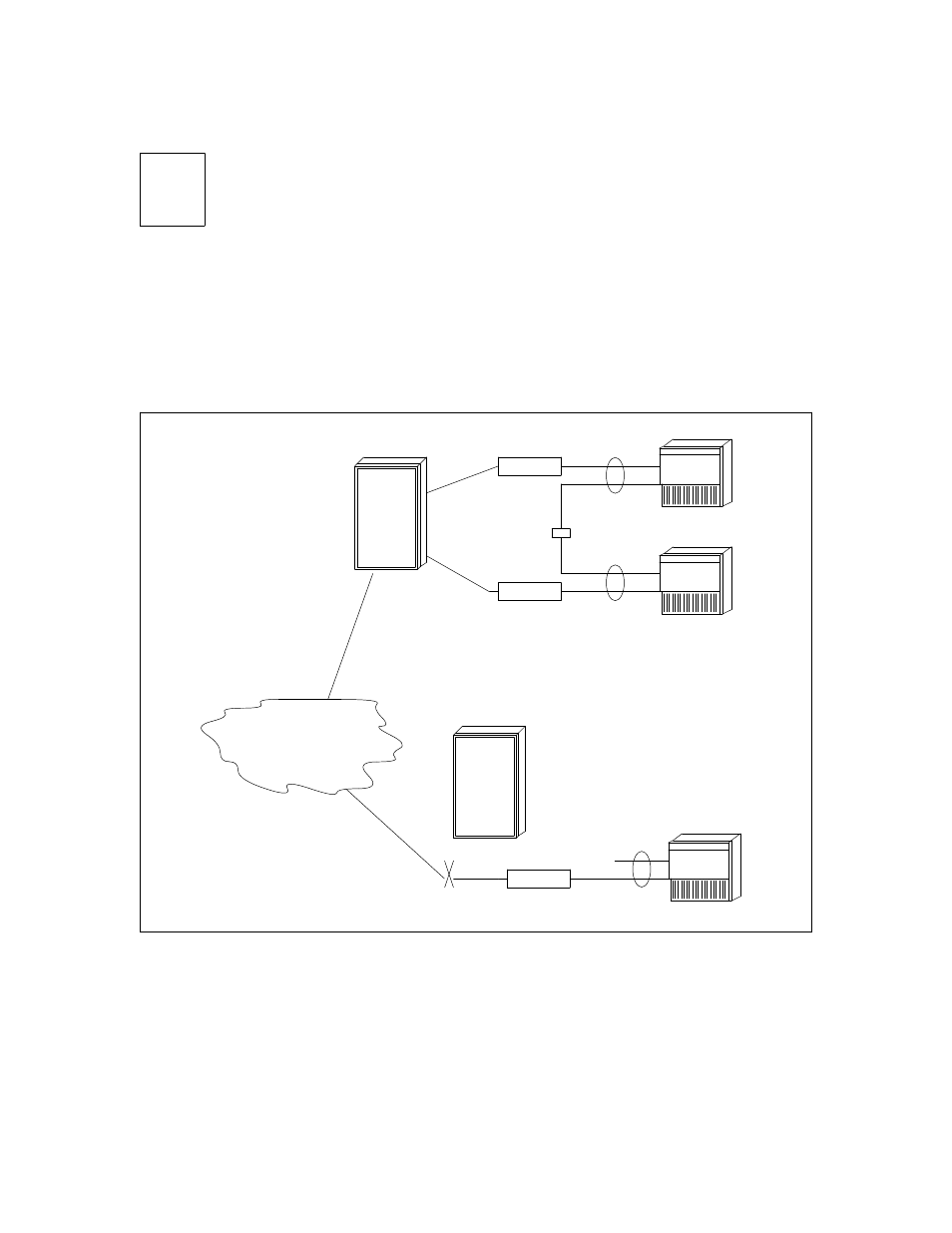
Switched EIA RS-232 Networks
3-5
_
______________________________________________________________________________________
_
______________________________________________________________________________________
_
______________________________________________________________________________________
NOTE
Equivalent modems such as the AT&T Paradyne DL424 instead of the DM424 modem could
be used.
The modem requires a connection through one of the switch’s analog ports or can connect directly to a CO
line. Switch analog port circuit packs are:
•
System 75, Generic 1, and Generic 3: TN742 or TN746B analog line circuit
•
System 85 and Generic 2 traditional module: SN222, SN228, or SN228B analog line circuit
•
System 85 and Generic 2 universal module: TN742 or TN746B analog line circuit
RS-232
AUDIX
NOT
USED
SWITCHED LINES
TO THE CENTRAL OFFICE
H600-330
GROUP 1
H600-331
GROUP 2
H600-331
GROUP 2
H600-331
GROUP 2
PUBLIC/PRIVATE
INTERLOCATION
FACILITIES
ALL CONNECTIONS
TO ANALOG PORTS
MODEM
T/R
T/R
T/R
T/R
T/R
SWITCH
SWITCH
RS-232
AUDIX
MODEM
RS-232
AUDIX
MODEM
Figure 3-3. Switched RS-232 Network for Separate Locations
If the modems must be located greater than 5.0 feet (1.524 meters) from the AUDIX system, an M25A RS-
232 extender cable is required for each. The modem must be within 50 feet (15.24 meters) of the AUDIX
system. The tip/ring circuit should be engineered by a switch representative.