Warning – GF Signet 4150 Turbidimeter User Manual
Page 5
5
Signet 4150 Turbidimeter
Electrical Connections
All of the electrical connections to the 4150 are made inside the
power supply, located to the right of the display.
The connections are labeled within the terminal box and are
self-descriptive.
Follow all local and government recommendations and methods
for installation of electrical connections to and between the
instrument and other peripheral devices.
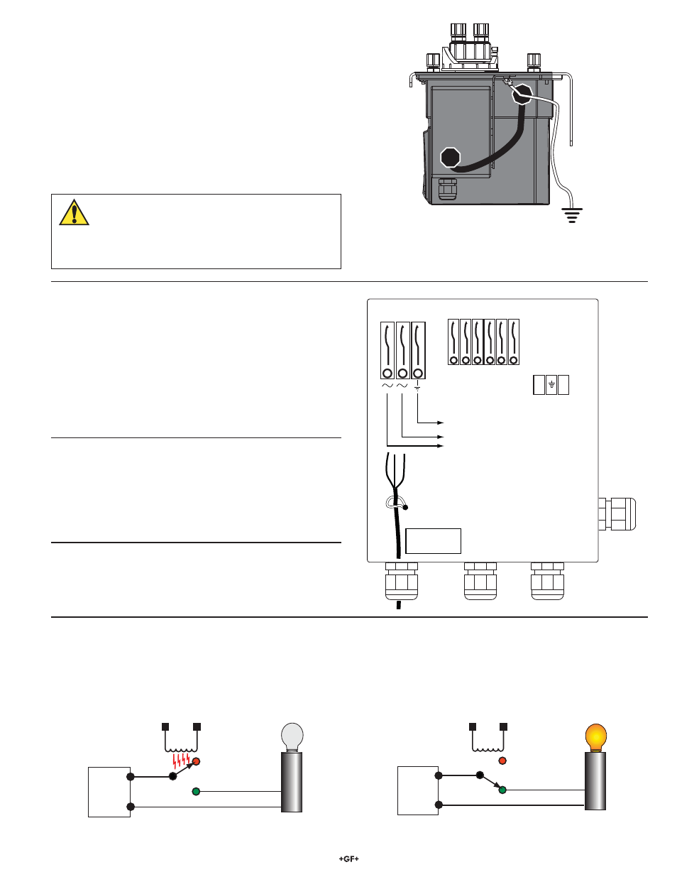
An external grounding terminal is provided for use in the most
extreme electrical noise environments. It is not required for most
installations.
This instrument requires AC voltages that can injure or kill.
Wiring should be done by quali¿ ed personnel only.
WARNING
V+
V-
Normal Operation
Normally Closed
Normally Open
Common
Relay
Coil
4150 Internal Power
External
Power
Supply
V+
V-
Normally Closed
Normally Open
Common
4150 Internal Power
External
Power
Supply
Alarm Condition
or Power Failure
Relay
Coil
NC
COM
NO
NC
COM
NO
ALARM2 ALARM1
+
-
A
B
}
4-20 mA
RS-485
Removable
Terminals
AC Cable
Restraint
115/230 VAC
Ground
90-250 VAC
47-63 Hz
Power
• Install a circuit breaker in the AC line before the 4150 power
connection to allow for service.
• The 4150 is not supplied with a power cord.
• The power cable bulkhead will accept cable diameters from 5.8
mm (0.23 in.) up to 10 mm (0.395 in.).
• All terminals are designed to accept wires in the range of
14 to 28 AWG.
• All wires should be stripped to a length of 6 mm (¼ in.).
• A strain relief strap is provided to reduce tension on the AC
power terminals.
RS-485
• The RS-485 half-duplex (2-wire) digital interface operates
with differential levels that are not susceptible to electrical
interferences.
• The last device on each bus requires terminating with a 120
resistor to eliminate signal reÀ ection on the line.
• Do not run RS-485 cables in the same conduit as power.
Relays
Both alarm relays are con¿ gured for fail-safe operation.
The normal condition is with power applied to the 4150 and in a non-alarm condition.
• The relays are rated for 2 A maximum.
• If power is removed from the 4150, the relays will be in an alarm state.
4 to 20 mA
• The active 4 to 20 mA output is driven by a 15 VDC power
source and can drive external loads up to 600 ohms.
• Do not run 4 to 20 mA cables in the same conduit as power.
Attach a wire to the small spade lug and connect the housing to a
local Earth ground if necessary.