Plumbing – GF Signet 4150 Turbidimeter User Manual
Page 4
4
Signet 4150 Turbidimeter
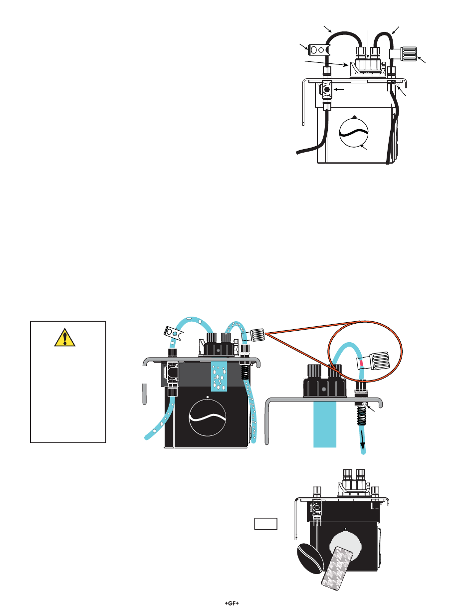
Adjust the Flow to Eliminate Bubbles
The cuvette must be free of air bubbles to provide accurate measurement. The 4150 provides two tools to make this adjustment.
Open the SHUTOFF CLAMP to allow water to À ow through the cuvette.
1. If the À ow is gravity-fed, remove the screw that is blocking the DRAIN VENT. This allows for atmospheric equalization and helps to
eliminate bubbles. The vent may leak for a few seconds, until the À ow is well established.
2. Adjust the BACKPRESSURE VALVE to prevent air from coming out of solution, which may be observed as tiny air bubbles in
the cuvette.
• Remove the measuring cuvette from the measuring cell and place it in the cuvette holder so it is visible while making these adjustments.
• If bubbles are visible inside the cuvette, turn the BACKPRESSURE VALVE until the bubbles disappear.
If bubbles are still visible inside the cuvette, a Stilling/Bubble Chamber, Signet part number 4150-0003 (159 001 587), can be ordered.
DESICCANT COMPARTMENT
OPEN ONLY FOR MAINTENANCE
Backpressure
Valve
Shutoff
Clamp
Backpressure
Valve
Drain vent
To Drain
Pressure
Regulator
The Inlet pressure
regulator is factory
set. Do not adjust!
Contact the factory
if inlet pressure
will exceed 50 psi!
A modi¿ ed tubing
connection may be
required.
Plumbing
• Use 8 mm (5/16 in.) OD, 5 mm (3/16 in.) ID À exible tubing for the water
supply connections.
• Opaque tubing (not supplied) should be used to prevent algae growth if the
tubing will be exposed to sunlight.
• The 4150 requires only 1 psi head pressure to operate.
• The À ow through cuvette is rated for a À ow of 100 mL/m to 1 L/m
(0.026 - 0.26 GPM).
• Inlet water pressure should not exceed 50 psi to avoid damage to the
tubing connection to the regulator.
• The integral pressure regulator is factory adjusted. Do not tamper
with the regulator.
• Fluid temperature must not exceed 50 °C (122 °F).
• The shutoff clamp is used to interrupt the À ow during cuvette maintenance.
• Route the sensor drain tubing to a suitable drain. Do not reintroduce the
drain sample to the process stream.
DESICCANT COMPARTMENT
OPEN ONLY FOR MAINTENANCE
Water
IN
from source
Measuring
Cuvette Assy
Desiccant access
Water
OUT
to Drain
Shutoff
Clamp
Pressure
Regulator
Backpressure
Valve
Drain Vent
Measuring
Cell
Install the Desiccant Pack: (See Fig. 4)
1. Locate the 3-4150.380 desiccant pack.
2. Remove the desiccant pack from its vacuum-sealed package.
3. Open the desiccant access door by turning it counterclockwise.
It is located on the left side of the Turbidimeter.
4. Place the desiccant pack into the instrument's body.
5. Reinstall the access door and rotate clockwise.
DESSICANT COMPARTMENT
OPEN ONLY FOR MAINTENANCE
Desiccant Pouch
3-4150.380
Fig. 4
NOTE: In regions where moisture or high humidity is prevalent, more
than one desiccant pouch may be needed, and desiccant may need
to be monitored more often.