Installation and commissioning, Preassembly – GF Signet 4150 Turbidimeter User Manual
Page 3
3
Signet 4150 Turbidimeter
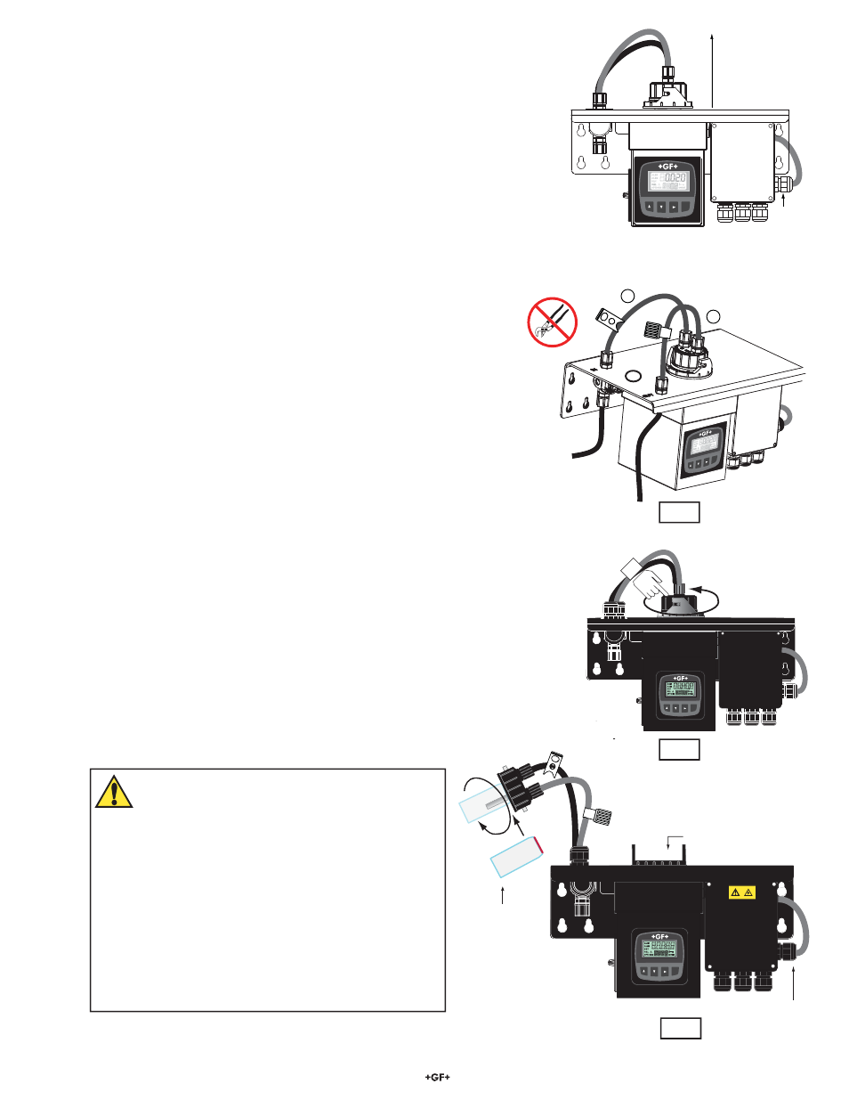
CAUTION!
Do not touch the glass surface of the cuvette!
Substances on the surface of the glass will cause errors
in the measurement.
Do not remove the glass cuvette from the cap while
holding the assembly over the measuring cell.
Do not allow any debris to fall into the measuring cell.
Do not leave the measuring cell open longer than
necessary. Extended exposure to the atmosphere may
shorten the effective life of the desiccant.
Installation and Commissioning
Mounting & Site Selection
The 4150 is designed to be wall mounted. All the necessary hardware is included.
• Mount the 4150 within 2 - 3 meters (6 - 10 ft) of the sampling point to ensure a quick
response time.
• It is recommended an isolation valve (NOT provided) be used to interrupt the inlet À ow
to the Turbidimeter.
• For ease of service there should be about 20 cm (8 in.) free area above the instrument
for calibration and cuvette maintenance.
• Choose a location that is easily accessible for operation and service.
• The display should be positioned at eye level.
• Four pan head screws and four wall anchors are provided to mount the wall bracket.
• The overall mounting dimensions of the instrument are shown on page 2. A mounting template is provided.
• Mount the Turbidimeter according to local electrical, building, and plumbing codes and seismic requirements.
Preassembly
Install Connection Tubes To The Measuring Cell:
1. Locate Tubing Kit 4150-0005 and install the tube kit with the shutoff clamp
(labeled “IN”) to the nipple assembly marked “IN” on the Turbidimeter and to the
measuring cell nipple marked "IN". See Fig. 1.
2. Install the tube kit with the small back pressure valve to the nipple assembly
marked “OUT” on the top right front corner of the turbidimeter and to the
measuring cell nipple marked “OUT”. See Fig. 1.
Note: Hand tighten only. Do not use any tools.
Install the Glass Cuvette: (See Fig. 2 and 3)
The Calibration Kit should be available for this procedure.
1. Locate and have ready the special cleaning cloth that comes with the Calibration
Kit.
2. Locate the glass measuring cuvette. Remove it from its shipping package. Do not
touch the glass. Take caution when handling the cuvette, being careful not to
scratch or mark the glass surface.
3. Unlock the measuring cell by holding the measuring cell with one hand and
twisting the measuring cell lock ring counter-clockwise.
4. Inspect the red gasket in the measuring cell for any defects, tears or dirt. Clean or
replace if necessary.
5. Carefully thread the glass cuvette on the measuring cell. Hand tighten, being
careful not to over tighten the cuvette. Over-tightening may cause the cuvette to
crack or break.
6. Clean the glass cuvette with the special cleaning cloth that comes in the
Calibration Kit. Do not use any other cloth.
7. Insert the measuring cell assembly back into the instrument and rotate the locking
ring clockwise to secure the assembly.
Signet Turbidimeter
ENTER
Measuring Cell
Sensor Interconnect cable
Cuvette
Fig. 3
Signet Turbidimeter
ENTER
Sensor
Interconnect
Cable
Provide 8 in. clearance
for maintenance.
Fig. 1
Signet T
urbidimeter
ENTER
1
2
Signet Turbidimeter
ENTER
Fig. 2