ELRO HIS20S Security & home automation system EXPANDED USERS MANUAL User Manual
Page 15
13
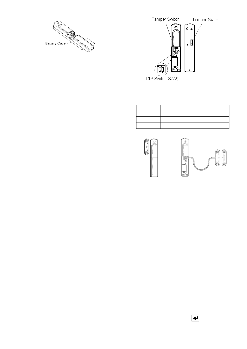
2. Fit the 3.6V Lithium battery supplied, with the
negative (-) towards the battery spring.
3. Mount the Detector to the fixed part of the frame
along the opening edge opposite the hinges using
either the double sided adhesive tape or screws
provided.
If fixing the Detector with screws; fit the Keyhole
slot in the top of the Detector over the head of the
smaller pan-head screw. Secure the bottom of
the Detector using the 12mm countersunk head
screw fitted within the battery compartment. You
will need to drill out the centre of the fixing screw
hole using a 3mm drill. Do not over tighten the
fixing screws as this may distort or damage the
casing.
4. Fit the Magnet to the moving part of the
door/window opposite the Detector using the
adhesive tape or 15mm fixing screws.
Ensure that the parallel gap between the Magnet
and Detector is less than 10mm and that the arrow
on the Magnet is pointing towards and aligned with
the mark on the Detector.
5. If several windows need to be protected, remove
the self-contained wired supplied and adopt the
wire according to the specifications as mentioned
below. This should be wired to the terminal block
provided in the battery compartment in series
connection. The wired contact should be
connected using two core (24AWG) wire of
maximum length 1.5m.
A cable entry cut-out is available and adjacent to
the terminal block.
6. Refit the battery cover.
SETTING THE MAGNETIC CONTACT
DETECTORS
1. Located on the PCB of the Detector is a
two-position DIP switch (SW2).
2. DIP switches 1-2 are used to enable/disable the
internal or external wired magnetic contact.
On/Off
Selection
DIP1 of SW2
DIP 2 of SW2
ON
Internal on
External on
OFF
Internal off
External off
Internal connection External wired connection
If setting the DIP1 & DIP2 to ‘Off’, only the internal
contact will be active. When two contacts are in
use for internal and external connection
simultaneously, one activation will be counted if one
of the contacts is opened; while both contacts must
be all close, the Detector will then be treated as
close.
3. If external contacts are wired to the Detector, set
the DIP1 to ‘Off’ and DIP2 to ‘On’.
IMPORTANT: If external contacts are not
connected, set the DIP1 to ‘On’ and DIP2 to ‘Off’
for the detector to operate correctly.
4. In order to communicate with the Smart Home Box,
the ID code of the Detector needs to be learned by
the Smart Home Box. To proceed with ID code
learning:
a. Set the Smart Home Box into ‘3. Security
Sensor Zone’ and press .