ELRO HIS20S Security & home automation system EXPANDED USERS MANUAL User Manual
Page 12
10
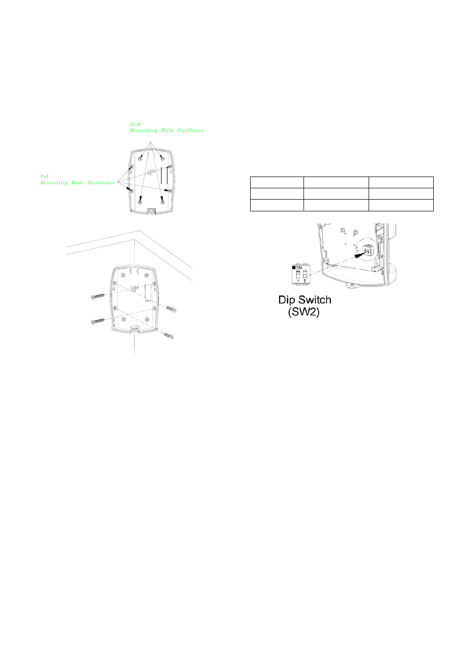
2. Carefully drill out the required mounting holes in
the rear cover using 3mm drill according to whether
the unit is being mounted in a corner or against a
flat wall.
Note: Using 1
st
mounting hole to fulfill corner
mounting installation, while 2
nd
mounting hole for
flat wall installation.
Corner mounting
3. Using the rear cover as a template, mark the
positions of the fixing holes on the wall.
4. Fix the rear cover to the wall using the two 18mm
No.4 screws and 25mm wall plugs, (a 5mm hole
will be required for the wall plugs). Do not
over-tighten the fixing screws as this may distort or
damage the cover.
5. Configure the PIR detector as described below.
Remember that on initial installation that the device
needs to be tested and should therefore be set in
Walk Test Mode.
6. Check that the detector PCB is located and set in
the correct position to provide the required
detection range. To adjust the PCB position,
simply slide it up or down ensuring that the location
legs are aligned with the required position number
marked on the board.
7. To refit the PIR detector to the rear cover and
locate the clips in the top edge into the rear cover.
Push the lower edge of the detector into place and
refit the fixing screw in the bottom edge of the PIR
to secure in position. Do not over-tighten the
fixing screws as this may damage the casing.
SETTING THE PIR DETECTORS
Located on the PCB of the PIR Detector is a
two-position DIP switch (SW2). When conducting the
Walk Test, ensure that the DIP switch SW2 is set as
follows:
SW2 DIP1
DIP2
ON
9
OFF
9
1. DIP1 of SW2 is used to configure the PIR Detector
for walk test mode, which allows the operation of
the detector to be checked during installation
without triggering a Full Alarm.
ON Walk Test mode
OFF Normal mode
Note: On initial installation the detector should be
set into Walk Test mode ready for testing. Upon
completion of Walk Test mode, set DIP1 of SW2 to
OFF for normal detection mode.
2. The PIR Detector incorporates an anti-false alarm
feature designed to compensate for situations
where the detector may be affected by
environmental changes, (e.g. insects, air
temperature, etc). This feature is called
“sensitivity detection” and may be selected for high
or low detection.
The recommended setting is for high sensitivity
detection. However, in cases of extreme
environmental problems or if unattributable false
alarms are experienced, it may be necessary to
select low sensitivity detection.