B&K Precision 2532B - Manual User Manual
Page 62
62
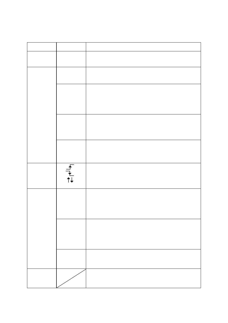
Table 13 - Edge Trigger Function Menu
Option
Setting
Explain
Type
Edge
With Edge highlighted, the rising or falling edge
of the input signal is used for the trigger.
Source
CH1
CH2
Triggers on a channel whether or not the
waveform is displayed.
EXT
Does not display the trigger signal; the Ext option
uses the signal connected to the EXT TRIG front-
panel BNC and allows a trigger level range of -
1.2 V to +1.2 V.
EXT/5
Same as Ext option, but attenuates the signal by a
factor of five, and allows a trigger level range of
+6 V to -6 V. This extends the trigger level
range.
AC Line
This selection uses a signal derived from the
power line as the trigger source; trigger coupling
is set to DC and the trigger level to 0 volts.
Slope
Trigger on Rising edge of the trigger signal.
Trigger on Falling edge of the trigger signal.
Trigger on Rising edge and Falling edge of the
trigger signal.
Mode
Auto
Use this mode to let the acquisition free-run in
the absence of a valid trigger. This mode scans
waveform at 100 ms/div or slower time base
settings.
Normal
Use this mode when you want to see only valid
triggered waveforms; when you use this mode,
the oscilloscope does not display a waveform
until after the first trigger.
Single
When you want the oscilloscope to acquire a
single capture of a waveform, press the
“SINGLE” button.
Set up
Enter the “Trigger Setup Menu” (See below
table).