3 install the rear cover, Chapter 2: hardware setup – Asus RS162-E4/RX4 User Manual
Page 22
Chapter 2: Hardware setup
-
2. Push the back side of the top
cover panel backward until it is
half inch away from the front
upper cover panel.
1/2 inch distance
3. Remove the back top cover panel.
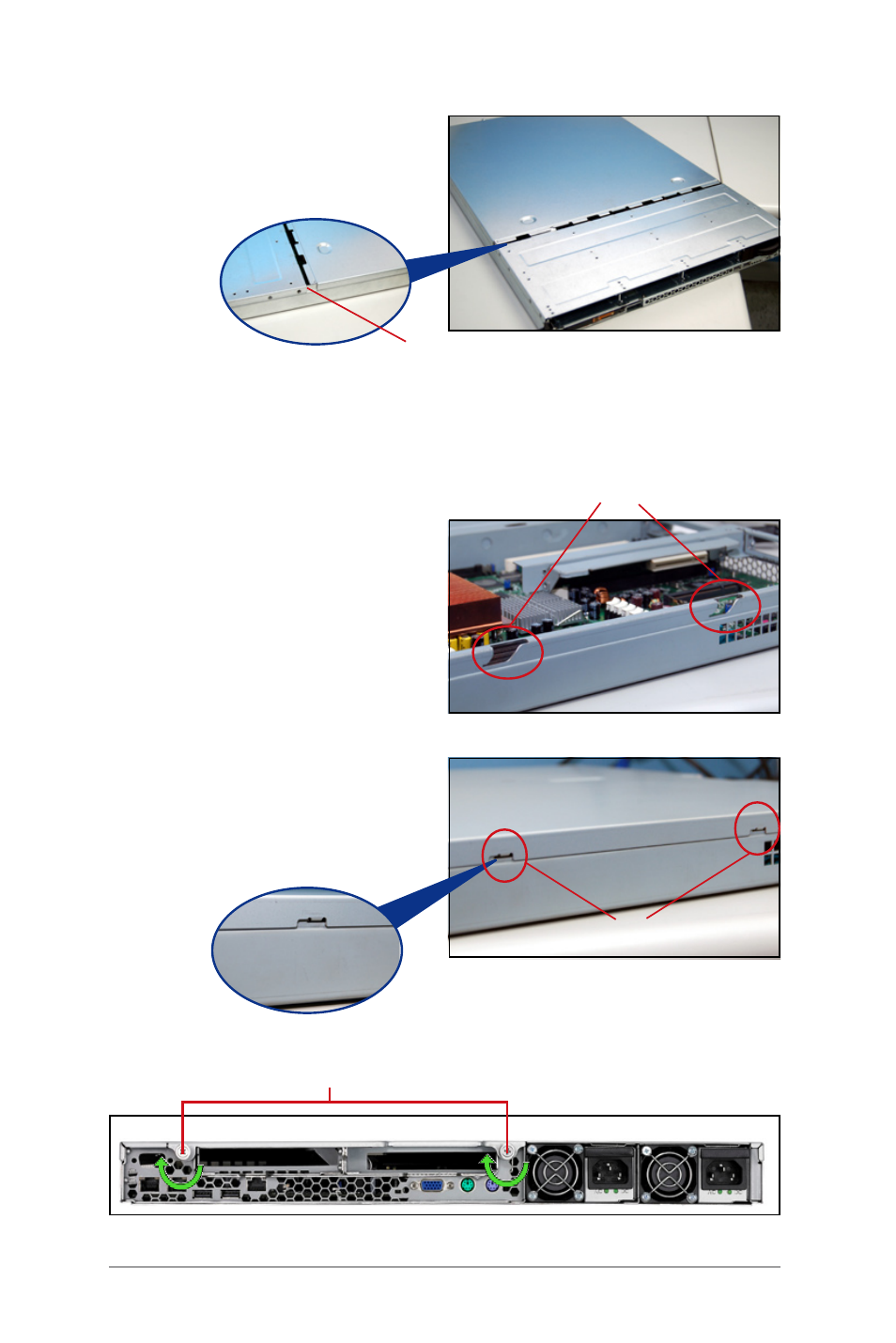
2.1.3 Install the rear cover
1. Locate the grooves (see the
figure). Push the top cover panel
toward the front panel.
Match the upper cover panel to the
grooves on the left and right sides.
2. Match the clips of the top cover
panel with the grooves (see the
figure), and then clinch. Leave
a half inch distence between
the front edge of the top cover
panel and the real panel.
firmly clinched
match the clips and the grooves
3. Fasten the two screws as shown below.
screws
See also other documents in the category Asus Computer hardware:
- AP2500 (40 pages)
- AP1700-S5 (58 pages)
- RS700-E6/ERS4 (138 pages)
- AP1600R-E2(AA2) (150 pages)
- P7F-E (162 pages)
- RS161-E4/PA2 (126 pages)
- RS163-E4/RX4 (11 pages)
- M2N-LR (113 pages)
- P5BV/SAS (184 pages)
- K8N-DRE (142 pages)
- RS161-E5/PA2 (124 pages)
- LSI SAS3442X-R (68 pages)
- ESC4000/FDR G2 (200 pages)
- PIKE 2208 (16 pages)
- ESC4000 (162 pages)
- ESC4000 (22 pages)
- PSCH-SR/IDE (102 pages)
- P9D-M (156 pages)
- RS740-E7-RS24-EG (212 pages)
- P5M2-E/4L (12 pages)
- ESC2000 G2 (226 pages)
- TS700-E6/RS8 (166 pages)
- RS160-E3/PS4 (140 pages)
- PU-DLS (134 pages)
- TR-DLSR (100 pages)
- P5BV-C/2L (161 pages)
- TS100-E5/PI4 (166 pages)
- ESC1000 Personal SuperComputer (184 pages)
- NRL-LS (120 pages)
- PCI-DA2200 (369 pages)
- P8C WS (140 pages)
- RS120-E4/PA4 (174 pages)
- P5MT-M (150 pages)
- TS Mini (114 pages)
- TS Mini (2 pages)
- TS Mini (112 pages)
- P5MT-MX/C (156 pages)
- AP140R-E1 (52 pages)
- AP140R-E1 (132 pages)
- ASMB6-iKVM (114 pages)
- DSBF-D16/SAS (200 pages)
- DSBF-D16 (202 pages)
- RS160-E5 (164 pages)
- Z8PE-D12X (170 pages)
- Z8PE-D12X (168 pages)