SENA ProBee-ZE20S-SEME User Manual
Page 42
ProBee-ZE20S-SExx User Guide Rev 1.8
42
Smart Energy GPIO is treated in this document. Please refer to ProBee-ZE20S User Guide for usage of
such options digital input, digital output and analog input.
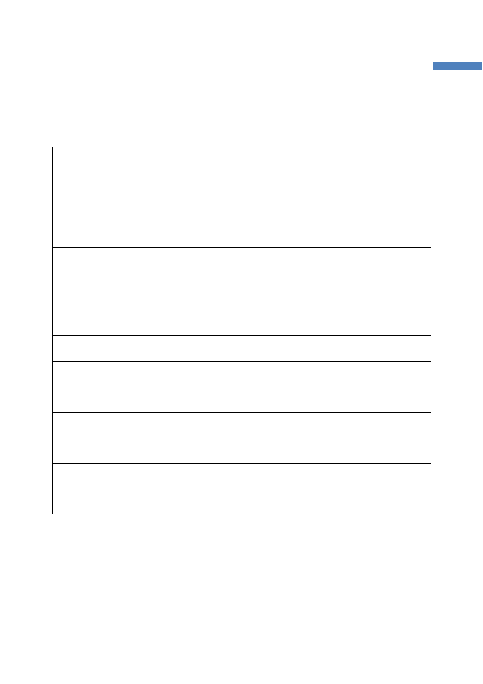
Table 4-2 Special GPIO Pins
Function
GPIO#
Type
Description
Factory_reset
/ Bootloader
-
DI
This input is dedicated for the factory reset button. If user wants to
restore the ZE20S device settings to factory default, this input (falling
edge, i.e. High to Low change) needs to be pressed for more than two
seconds. It will be applied after the input released again. If this input is
pressed while the ZE20S starts, the local node enters bootloader
menu and it is possible to upload the firmware. Factory reset button is
not available when the ZE20S device is sleeping.
Permit_joining
/ Wake-up
0
DI
This input (falling edge, i.e. High to Low change) is used to permit
joining or interrupt sleeping. This function is activated when GPIO0 is
set to 5. The functions depend on the node type of the ZE20S. If the
node is set to coordinator or router, this input works to permit other
nodes joining for Permit joining timeout(S-register 22 value). If the
node is set to sleepy end-device, it is used for wake-up signal when
the node is sleeping.
UART_CTS
1
DI
This input is used for UART CTS if GPIO1 is set to 5. It should be
enabled when CTS flow control is used.
UART_RTS
2
DO
This output is used for UART RTS if GPIO2 is set to 5. It should be
enabled when RTS flow control is used.
UART_DTR
3
DO
This output is used for UART DTR if GPIO3 is set to 5.
UATR_DSR
4
DI
This input is used for UART DSR if GPIO4 is set to 5.
Power LED
15
DO
If GPIO15 is set to 5, this output turns ON (High) when power is
supplied. If the node is set to an end-device, it will blink periodically.
Please refer to 8 S-Registers for S14 regarding the management of
the LED status.
Status LED
16
DO
If GPIO16 is set to 5, this output turns ON (High) when the device
joins a network, blinks when joining is permitted, and turns OFF (Low)
when leaves the network. Please refer to 8 S-Registers for S14
regarding the management of the LED status.