3B Scientific Optical Bench U, 1200 mm User Manual
Page 21
21
•
Arrange the two polarization filters together and
then rotate them until they permit most of the light
to pass through. Place them in this position into
the object holders.
•
The object holder serves as the polarizer, the rotat-
able holder as analyzer.
•
Turn the rotatable holder until the lamp's filament
wire can no longer be seen on the screen. The fil-
ters are then crossed at right angles.
•
Use the round cell to place a sugar solution on the
prism table and then place the lens f = +100 mm
at the 37.5 cm position.
•
Due to the sugar solution a rotation occurs in the
polarization plane resulting in light passing through
again and appearing on the screen.
•
Just to what extent the analyzer has to be turned to
block out the light depends on the sugar solution's
concentration.
Experiment 23: Direct-vision (Amici) prism,
absorption spectrum
23.1 Equipment:
•
Optical bench U17150
•
Experimental lamp U17140
•
Prism table U17020
•
Adjustable slot U17015
•
Holder for the direct-vision prism U17025
•
Direct-vision prism (Amici) U14020
•
Concave lens f = +50 mm U17101
•
Concave lens f = +100 mm U17102
•
Cell, rectangular U17129
•
Set of color filters U21878
•
Projection screen U17125
•
5 optical riders 75 mm U17160
•
1 optical rider 30 mm U17161
•
Potassium permanganate (KMnO
4
)
•
Plug-in power supply unit U13900
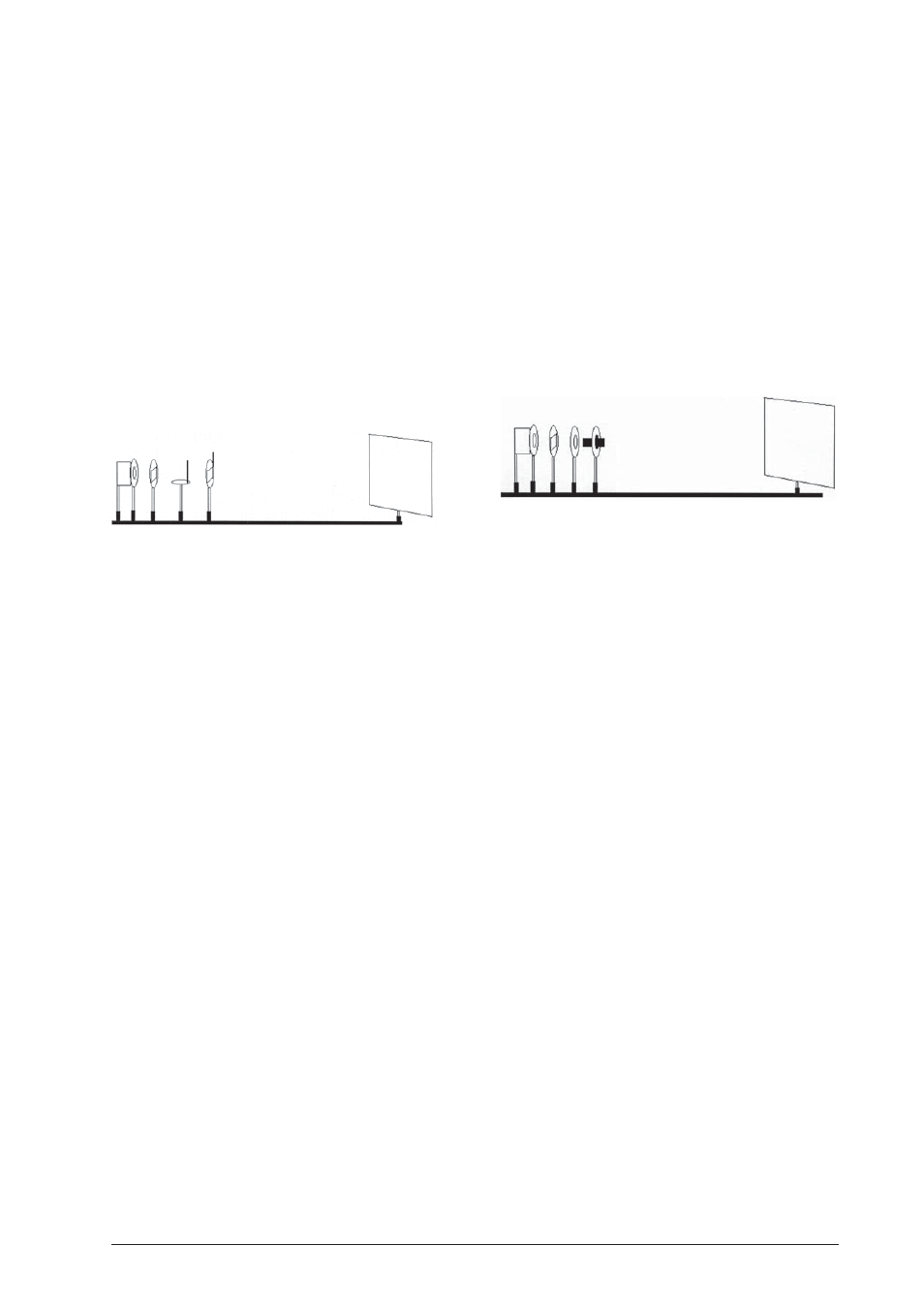
23.2 Set up
•
Place the experimental lamp vertically at the 0 po-
sition.
•
Set up the lens f = +50 mm at the 8.5 cm position.
•
Place the adjustable slit at the 14 cm position.
•
Position the lens f = +100 mm at 8.5 cm.
•
Set up the projection screen at 100 cm.
23.3 Procedure
•
By sliding the lens f = +100 mm a sharply focussed
image of the slit is produced on the screen. The
image should be approx. 3 mm wide.
•
Position the direct-vision prism in the holder at
26.5 cm so that the polished edges are in a perpen-
dicular position and the light beam travels through
the middle. If necessary correct using the light
source and the image lens.
•
By regulating the adjustable slit the spectrum can
be set with more intensity and sharper focus.
•
This set-up is the basic configuration for all exper-
iments using the direct-vision (Amici) prism.
•
Since the halogen lamp is a solid body, the spec-
trum dealt with here is a continuous spectrum.
•
If a color filter (e.g. red) is placed in front of the
prism, a black band is produced instead of red in
the spectrum. This spectrum is the absorption spec-
trum.
•
Instead of a color filter you can also use a cell, filled
with a solution of potassium permanganate in wa-
ter, for example, which is placed on the prism ta-
ble in front of the prism. This results in the gener-
ation of several black bands in the spectrum.
Experiment 24: Line spectrum
24.1 Equipment:
•
Optical bench U17150
•
Ballast for spectral lamps U21905
•
Spectral lamps e.g. U13033
•
Adjustable slit U17015
•
Holder for direct-vision prism U17025
•
Direct-vision prism U14020
•
Concave lens f = +50 mm U17101
•
Concave lens f = +100 mm U17102
•
Projection screen U17125
•
5 optical riders 75 mm U17160
•
1 optical rider 30 mm U17161
•
Plug-in power supply unit U13900
24.2 Set up 1
•
Place the holder with the spectral lamp at the 0
position.
•
Set up lens f = +50 mm at the 5 cm position.
•
Position adjustable slit at 10 cm.
•
Place lens f = +100 mm at the 21.5 cm position.
•
Set up the projection screen at 100 cm.
24.3 Procedure
•
After switching the spectral lamp on wait for ap-
proximately 5 minutes until the lamp lights up to
its maximum brightness.
•
By sliding lens f = +100 mm a sharper image of
the slit is produced on the screen.
•
Position the direct-vision prism in the holder at
26.5 cm so that the polished surfaces are perpen-
dicular and the light beam passes through their
center. If necessary correct the image lens using
the light source.
•
A line spectrum of mercury is produced.
•
The spectrum can be set more brightly and in sharp-
er focus by regulating the adjustable slit.