3B Scientific Optical Bench U, 1200 mm User Manual
Page 19
19
•
In actual practice the chromatic aberration of lenses
is eliminated to large degree by a combination of
converging and diverging lenses.
•
Lenses without spherical aberration are called as-
pherical lenses while those without chromatic ab-
erration are called achromatic lenses.
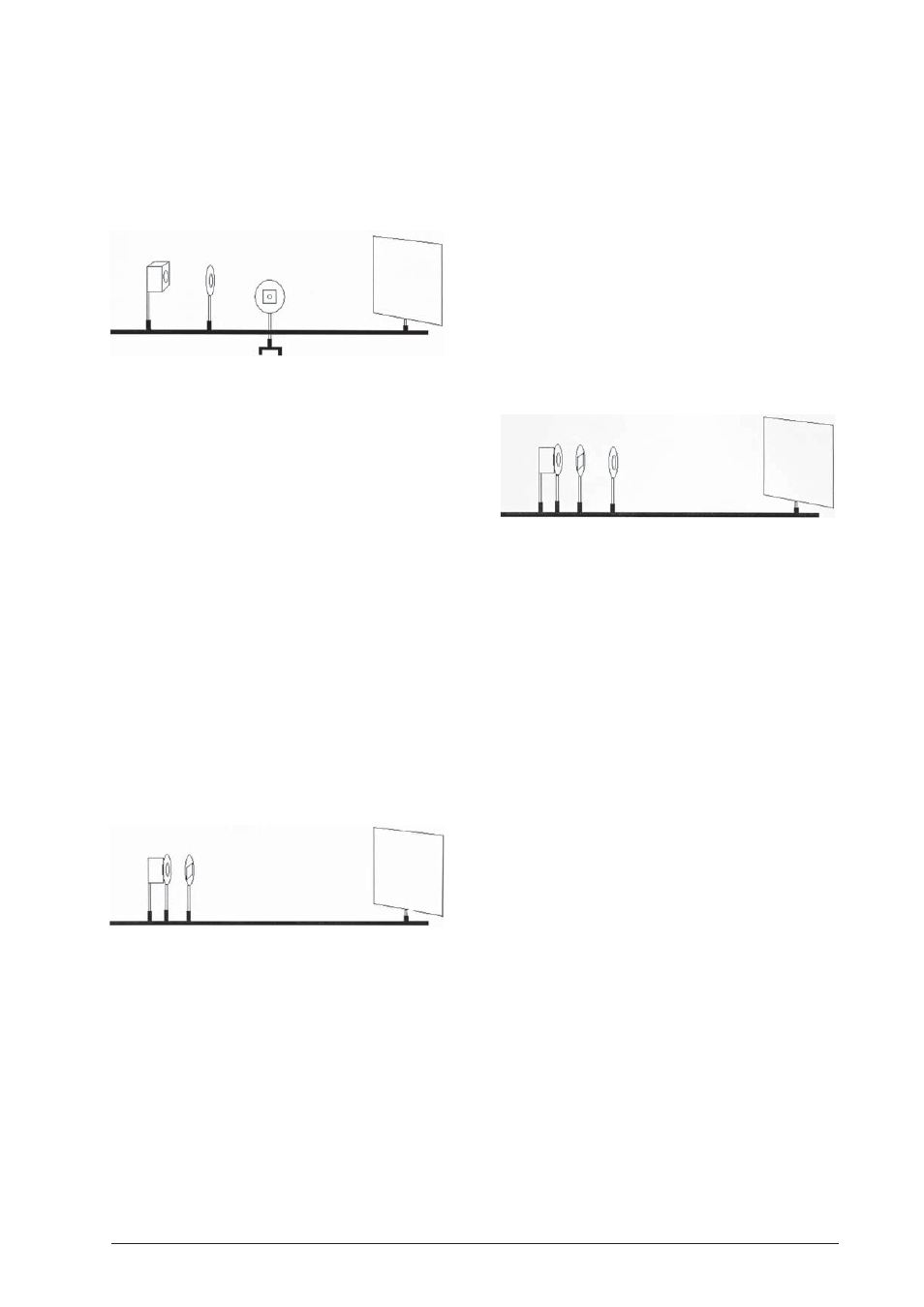
Experiment 16: Model of a camera obscura
16.1 Equipment:
•
Optical bench U17150
•
Experimental lamp U17140
•
Object holder, shaft-mounted U17000
•
Slide with the letter “F” from U17040
•
Concave lens f = +150 mm U17103
•
Projection screen U17125
•
3 optical riders 75 mm U17160
•
1 optical rider 30 mm U17161
•
Plug-in power supply unit U13900
16.2 Set up
•
Place the experimental lamp vertically at the 0 po-
sition.
•
Set the holder with slide up at the 14 cm position.
•
Place the lens f = +150 mm at the 32 cm position.
•
Set up the projection screen at the 84 cm position.
16.3 Procedure
•
The letter “F” is produced on the screen in a sharp
and inverted image.
Experiment 17: Model of a slide projector
17.1 Equipment:
•
Optical bench U17150
•
Experimental lamp U17140
•
Object holder, shaft-mounted U17000
•
Slide
•
Concave lens f = +50 mm U17101
•
Concave lens f = +100 mm U17102
•
Iris U17010
•
Projection screen U17125
•
5 optical riders 75 mm U17160
•
1 optical rider 30 mm U17161
•
Plug-in power supply unit U13900
17.2 Set up
•
Place the experimental lamp vertically at the 0 po-
sition.
•
Set up the condenser lens f = +50 mm at the 10 cm
position.
•
Place the object holder at the 15 cm position. The
slide must be inserted into the holder upside down.
•
Position the lens f = +100 mm at 27 cm.
•
Position the projection screen at 100 cm.
17.3 Procedure
•
The lens f = +100 mm serves as the lens (objec-
tive). The slide is reproduced as a sharp image on
the screen. The sharpness of the image can be cor-
rected by shifting the position of the light source.
•
Lens errors can be eliminated by placing the iris at
the 38 cm position.
Experiment 18: Model of a microscope
18.1 Equipment:
•
Optical bench U17150
•
Experimental lamp U17140
•
Object holder, shaft-mounted U17000
•
Concave lens f = +50 mm U17101
•
Concave lens f = +100 mm U17102
•
Concave lens f = +150 mm U17103
•
Iris U17010
•
Projection screen U17125
•
5 optical riders 75 mm U17160
•
1 optical rider 30 mm U17161
•
Plug-in power supply unit U13900
18.2 Set up
•
Place the experimental lamp vertically at the 0 po-
sition.
•
Set up the object holder at the 25 cm position. A
coin serves as the object. This can be attached to
the center of the holder using adhesive tape.
•
Place lens f = +50 mm at the 30 cm position.
•
Set the lens f = +100 mm up at the 54 cm position.
•
Set the projection screen up at the 100 cm posi-
tion.
18.3 Procedure
•
Lens f = +50 mm serves as the objective.
•
Lens f = +100 mm reproduces a sharp image of
the object on the screen.
•
Switch the light off and remove the screen.
•
Place the lens f = +150 mm at the 74 cm position.
In conjunction with the lens f = +100 mm it forms
the ocular.
•
The virtual image of the coin can be perceived as if
one were looking through the lens f = +150 mm.