3B Scientific Optical Bench U, 1200 mm User Manual
Page 18
18
Experiment 13: Lens error, spherical aberration 1
13.1 Equipment:
•
Optical bench U17150
•
Experimental lamp U17140
•
Object holder, shaft-mounted U17000
•
Diaphragm with five-fold slot from U17040
•
Concave lens f = +50 mm U17101
•
Concave lens f = +150 mm U17108
•
Iris U17010
•
Projection screen U17125
•
5 optical riders 75 mm U17160
•
1 optical rider 30 mm U17161
•
Plug-in power supply unit U13900
13.2 Set up
•
Place the experimental lamp vertically on the rail
at the 0 position.
•
Set up the lens f = +150 mm at the 21 cm position.
•
Place the holder with horizontal fivefold slit at the
26 cm position.
•
Position the projection screen at 50 cm.
13.3 Procedure
•
In thin lenses parallel light rays are refracted dif-
ferently at the areas around the edge and in the
middle section of the lens so that more than one
focal points arise. This phenomenon is referred to
as spherical aberration.
•
5 parallel light beams are produced using the five-
fold slot and the lens.
•
Realign the screen on the optical bench so that the
beam runs along the face of the screen. If neces-
sary, rotate the lamp as well.
•
Place the lens f = +50 mm directly in front of the
screen (at approx. 36 cm). The focal point, the con-
verging and diverging rays are now clearly visible.
Note the position of the focal point on the screen.
•
Using the iris (at a position of approx. 31 cm) the
rays around the edges can now be blocked out. It is
possible now to observe a shift of the focal point
and the focal point is considerably sharper in fo-
cus.
Experiment 14: Lens error, spherical aberration 2
14.1 Equipment:
•
Optical bench U17150
•
Experimental lamp U17140
•
Object holder, shaft-mounted U17000
•
Apertured diaphragm U17040
•
Concave lens f = +50 mm U17101
•
Projection screen U17125
•
3 optical rider 75 mm U17160
•
1 optical rider 30 mm U17161
•
Plug-in power supply unit U13900
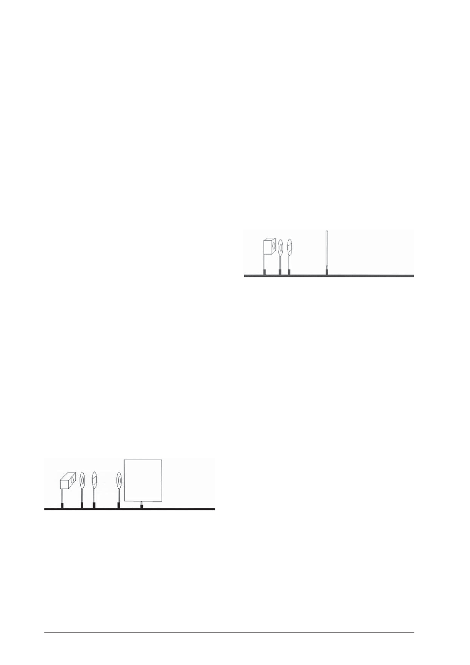
14.2 Set up
•
Place the experimental lamp vertically on the rail
at the 0 position.
•
Set up the lens f = +50 mm at the 11 cm position.
•
Place the holder with the iris at the 6 cm position.
•
Set up the projection screen at the 50 cm position.
14.3 Procedure
•
Use the lens to focus the image of the lamp's fila-
ment as sharply as possible on the screen.
•
Place the apertured diaphragm on the optical
bench. An even sharper image is produced by elim-
inating the light rays around the edges.
•
The change in the image's sharpness is caused by a
shift of the focal point.
Experiment 15: Lens error chromatic aberration
15.1 Equipment:
•
Optical bench U17150
•
Experimental lamp U17140
•
Object holder, shaft-mounted U17000
•
Apertured diaphragm from U17040
•
Concave lens f = +150 mm U17103
•
Projection screen U17125
•
3 optical riders 75 mm U17160
•
1 optical rider 30 mm U17161
•
Plug-in power supply unit U13900
15.2 Set up
•
Place the experimental lamp vertically on the rail
at the 0 position.
•
Set the lens f = +150 mm up at the 23 cm position.
•
Position the projection screen at 95 cm.
15.3 Procedure
•
Use the lens to focus the image of the lamp's fila-
ment as sharply as possible on the screen.
•
By shifting the screen to the right the edge of the
image turns a shade of blue. If the screen is shifted
to the left, then the color of the edge starts turning
a shade of red.
•
This color change is caused by the fact that the light
rays in the center of the lens are refracted differ-
ently than the ones on the edge of the lens. This
phenomenon is called color shift or chromatic ab-
erration.
•
If the apertured diaphragm is placed behind the
lens (at the 28 cm position) an extremely sharply
focused image of the lamp filament appears with-
out chromatic aberration.