3B Scientific Optical Bench U, 1200 mm User Manual
Page 13
13
•
Object holder, shaft mounted U17000
•
Diaphragm with single slit from U17040
•
Convex lens f = +150 mm U17108
•
Optical disc U17128
•
Plane mirror from U17128
•
3 optical riders 75 mm U17160
•
1 optical rider 30 mm U17161
•
Plug-in power supply U13900
2.2 Set up
•
Place the experimental lamp horizontally on the
rail at the 10 cm position.
•
Place the object holder with single-slit diaphragm
horizontally on the rail at the 20 cm position.
•
Place the concave lens at the 25 cm position.
•
Mount the optical disc with plane mirror on a small
optical rider at the 40 cm position.
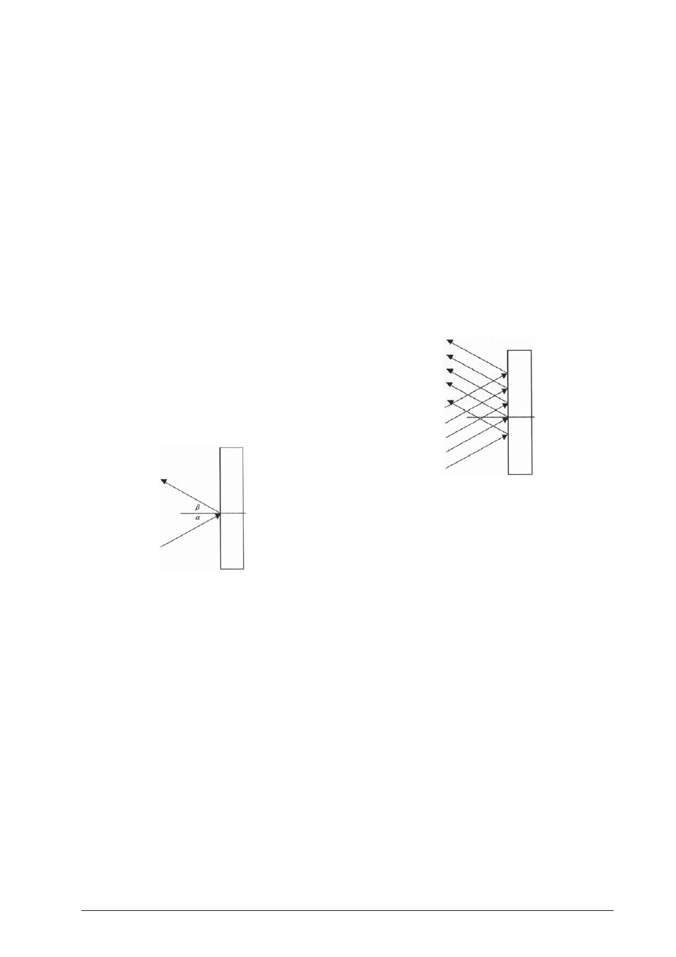
2.3 Procedure
•
Fasten the plane mirror mounted on the optical
disc to the 90° to -90° line.
•
Set the height of the disc so that the incident light
ray is reflected from the 0° line.
•
By rotating the disc we can verify the law of reflec-
tion, which states that the angle of incidence is
equal to the angle of reflection.
Experiment 3: Reflection of a light beam from a
plane mirror
3.1 Equipment:
•
Optical bench U17150
•
Experimental lamp U17140
•
Object holder, shaft-mounted U17000
•
Fivefold slit from U17040
•
Convex lens f = +150 mm U17108
•
Optical disc U17128
•
Plane mirror from U17128
•
3 optical riders 75 mm U17160
•
1 optical rider 30 mm U17161
•
Plug-in power supply unit U13900
3.2 Set up
•
Place the experimental lamp horizontally on the
rail at the 10 cm position.
•
Place the object holder with the five-fold slit at the
20 cm position.
•
Place the convex lens at the 25 cm position.
•
Attach the optical disc with plane mirror to the
small rider positioned at 40 cm.
3.3 Procedure
•
Attach the plane mirror on the optical disc at the
90°-90° line.
•
Adjust the height of the disc so that the middle ray
of light propagates along the 0° line and all rays
are reflected into each other.
•
By rotating the disc it is demonstrated that a paral-
lel incident beam of light is also parallel after be-
ing reflected.
•
By moving the lens away from the light source it
can be demonstrated that a converging light beam
is also reflected as a converging light beam.
•
Without the use of the convex lens it can be dem-
onstrated that a divergent light beam also diverges
upon reflection.
Experiment 4: Reflection of a light beam from a
concave or convex mirror
4.1 Equipment:
•
Optical bench U17150
•
Experimental lamp U17140
•
Object holder, shaft-mounted U17000
•
Fivefold slit from U17040
•
Concave lens f = +150 mm U17108
•
Optical disc U17128
•
Mirror from U17128
•
3 optical riders 75 mm U17160
•
1 optical rider 30 mm U17161
•
Plug-in power supply U13900
4.2 Set up
•
Place the experimental lamp horizontally on the
rail at the 10 cm position.
•
Place the object holder with five-fold slit horizon-
tally on the rail at the 20 cm position.
•
Place the convex lens at the 25 cm position.
•
Place the optical disc with convex mirror on the
small rider at the 40 cm position.
4.3 Procedure
•
Fasten the concave mirror on the optical disc on
the 90°-90° line.
•
Adjust the height of the disc so that the middle ray
of light travels along the 0° line and is reflected
into itself.