3B Scientific Optical Bench U, 1200 mm User Manual
Page 15
15
6.3 Procedure
•
Fasten the trapezoidal body on the optical disc
along the 90° to -90° line so that its long side faces
the light source. The middle section of the trape-
zoidal body acts like a plane-parallel plate.
•
Adjust the height of the disc so that the incident-
ing light beam propagates on the 0° line and is not
refracted by the trapezoidal body.
•
Rotate the disc so that the beam is now refracted.
•
The direction of the outgoing light ray is not al-
tered.
•
The outgoing light ray is nevertheless diverted from
its original path by a distance d. For a plate of h
density, this gives the following for d:
(
)
α −β
=
β
sin
cos
d
h
Experiment 7: Refraction at a prism
7.1 Equipment:
•
Optical bench U17150
•
Experimental lamp U17140
•
Object holder shaft-mounted U17000
•
Diaphragm with single slit from U17040
•
Concave lens f = +150 mm U17108
•
Optical disc U17128
•
Trapezoidal body from U17128
•
Right-angled prism from U17128
•
3 Optical rider 75 mm U17160
•
1 Optical rider 30 mm U17161
•
Plug-in power supply unit U13900
7.2 Set up
•
Place the experimental lamp at the 5 cm position.
•
Set up the object holder with diaphragm including
single slit at the 20 cm position.
•
Place the concave lens at the 25 cm position.
•
Set the optical disc with trapezoidal body on the
small optical rider at the 40 cm position.
7.3 Procedure
•
Fasten the trapezoidal body onto the optical disc
along the 90° to -90° line so that the pyramid points
upwards.
•
Adjust the height of the disc so that the incident
light ray travels on the 0° line.
•
After the disc is rotated, the light ray incidents on
the upper section of the trapezoidal body, which
now functions, like a prism.
•
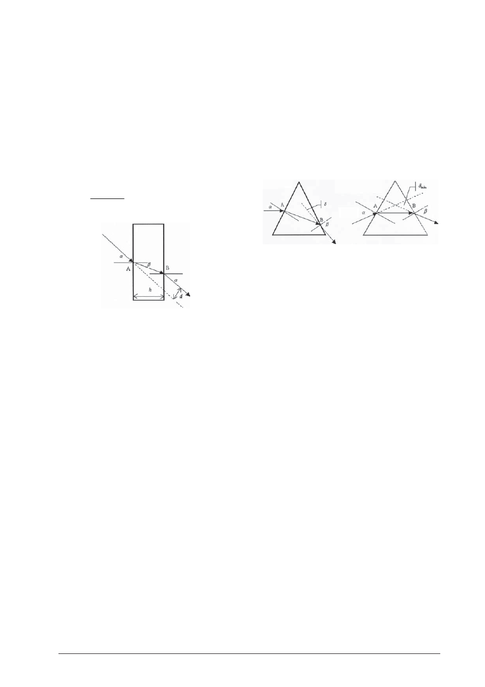
In an acrylic prism the light ray incident at point A
is refracted from the axis of incidence. At the emerg-
ing point B the ray is refracted away from the axis
of incidence. The sum total of all refraction angles
is called the deflection angle
δ
. This is the angle
between the incident and emerging light rays.
•
It can be demonstrated that the incident angle
α
at the minimum deflection angle
δ
min
is equal to
the emerging angle ß. The refracted ray then prop-
agates inside the prism parallel to the side, which
is not passed through.
Experiment 8: Inverting prisms
8.1 Equipment:
•
Optical bench U17150
•
Experimental lamp U17140
•
Object holder shaft-mounted U17000
•
Diaphragm with single and fivefold slit from U17040
•
Concave lens f = +150 mm U17108
•
Optical disc U17128
•
Right-angled prism from U17128
•
3 Optical rider 75 mm U17160
•
1 Optical rider 30 mm U17161
•
Plug-in power supply unit U13900
8.2 Set up
•
Place the experimental lamp horizontally on the
rail at the 5 cm position.
•
Place the object holder including a diaphragm with
single or five-fold slot horizontally on rail at the
20 cm position.
•
Set up the concave lens at the 25 cm position.
•
Set the optical disc with right-angled prism on the
small optical rider at the 40 cm position.
8.3 Procedure
•
Fasten the right-angled prism on the optical disc
along the 90°-90° line so that the right angle is lined
up with the 0° line and faces the light source.
•
Adjust the height of the disc so that the incident
light beam propagates on the 0° line.
•
By rotating the disc all of the previously described
phenomena can be observed.
•
At a certain angle (limiting angle) the ray is subject
to total internal reflection.
•
Using the diaphragm with fivefold slit, it can be
demonstrated that the rays can be reflected back
in the direction from which they came.