Pin description – Rainbow Electronics AT75C220 User Manual
Page 74
AT75C220
74
USART: Universal Synchronous/Asynchronous Receiver/Transmitter
The AT75C220 provides two identical full-duplex, universal
synchronous/asynchronous receiver/transmitters as
USART A and USART B. These peripherals sit on the APB
bus but are also connected to the ASB bus (and hence
external memory) via a dedicated DMA.
The main features are:
• Programmable baud rate generator
• Parity, framing and overrun error detection
• Line break generation and detection
• Automatic echo, local loopback and remote loopback
channel modes
• Multi-drop mode: address detection and generation
• Interrupt generation
• Two dedicated peripheral data controller channels
• 6-, 7- and 8-bit character length
• Modem control signals
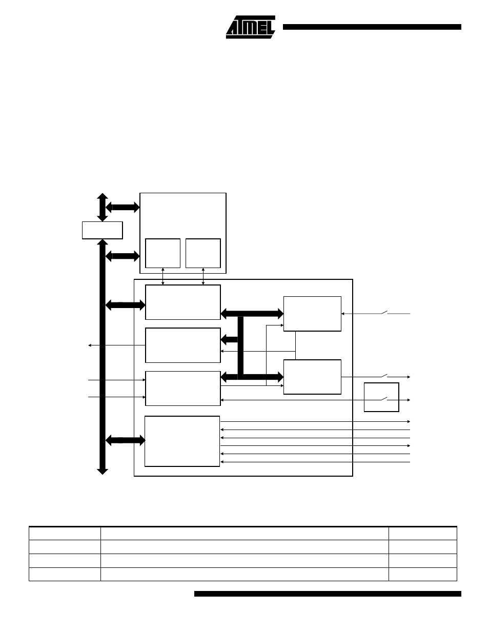
Figure 15. USART Block Diagram
Pin Description
Each USART channel has external signals as defined in Table 22.
Peripheral Data Controller
Receive
Channel
Transmit
Channel
Control Logic
Interrupt Control
Baud Rate Generator
Receiver
Transmitter
AMBA
ASB
APB
USxIRQ
ACLK
ACLK/8
RXD
TXD
SCK
USART Channel
Baud Rate Clock
PIO A
Modem Control
NRTS
NCTS
NRI
NDSR
NDTR
NDCD
Table 22. USART External Signals
Signal Name
Description
Type
SCK
USART Serial Clock. Can be configured as input or output. See US_MR
I/O
TXD
Transmit Serial Data
Output
RXD
Receive Serial Data
Input