Tc channel mode register: capture mode – Rainbow Electronics AT75C220 User Manual
Page 110
AT75C220
110
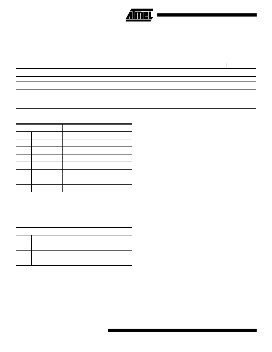
TC Channel Mode Register: Capture Mode
Register Name:TC_CMR
Access Type:Read/write
Reset Value: 0x0
•
TCCLKS: Clock Selection
•
CLKI: Clock Invert
0 = Counter is incremented on rising edge of the clock.
1 = Counter is incremented on falling edge of the clock.
•
BURST: Burst Signal Selection
•
LDBSTOP: Counter Clock Stopped with RB Loading
0 = Counter clock is not stopped when RB loading occurs.
1 = Counter clock is stopped when RB loading occurs.
•
LDBDIS: Counter Clock Disable with RB Loading
0 = Counter clock is not disabled when RB loading occurs.
1 = Counter clock is disabled when RB loading occurs.
31
30
29
28
27
26
25
24
–
–
–
–
–
–
–
–
23
22
21
20
19
18
17
16
–
–
–
–
LDRB
LDRA
15
14
13
12
11
10
9
8
WAVE
CPCTRG
–
–
–
ABETRG
ETRGEDG
7
6
5
4
3
2
1
0
LDBDIS
LDBSTOP
BURST
CLKI
TCCLKS
TCCLKS Clock
Selected
0
0
0
ACLK/2
0
0
1
ACLK/8
0
1
0
ACLK/32
0
1
1
ACLK/128
1
0
0
ACLK/1024
1
0
1
XC0
1
1
0
XC1
1
1
1
XC2
BURST
0
0
The clock is not gated by an external signal.
0
1
XC0 is ANDed with the selected clock.
1
0
XC1 is ANDed with the selected clock.
1
1
XC2 is ANDed with the selected clock.