Ds1862 xfp laser control and digital diagnostic ic, Detailed register description – Rainbow Electronics DS1862 User Manual
Page 30
DS1862
XFP Laser Control and Digital Diagnostic IC
30
____________________________________________________________________
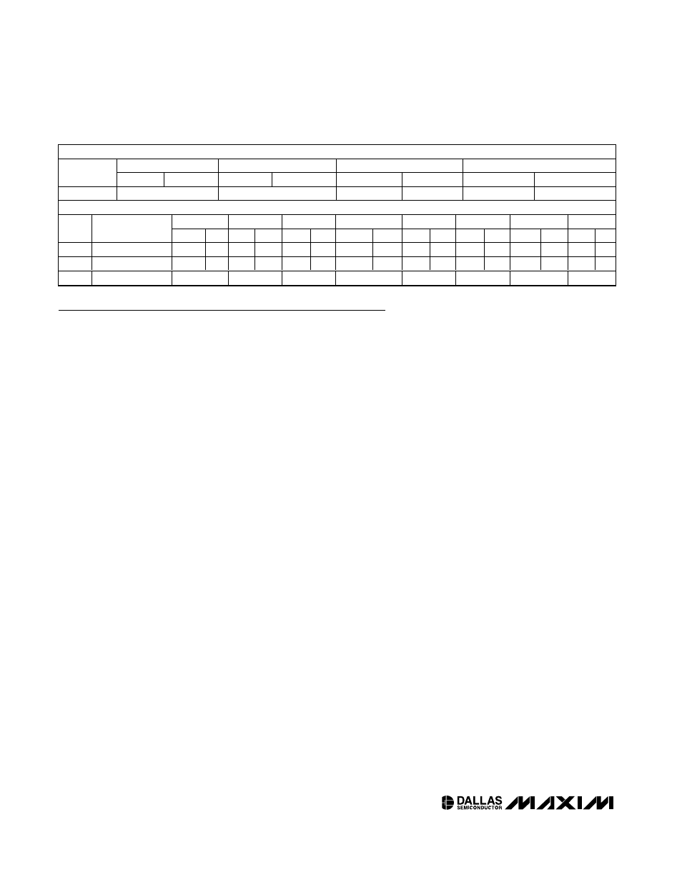
TABLE 05H (OPTIONAL OFFSETS AND THRSET)
WORD 0
WORD 1
WORD 2
WORD 3
ADDRESS
(hex)
Byte 0/8
Byte 1/9
Byte 2/A
Byte 3/B
Byte 4/C
Byte 5/D
Byte 6/E
Byte 7/F
80–87
DS60 SCALE
LM50 SCALE
Reserved
Reserved
Reserved
V
TH
DAC Value
<1>
EXPANDED BYTES
Bit7
Bit6
Bit5
Bit4
Bit3
Bit2
Bit1
Bit0
BYTE
(hex)
BYTE/WORD
NAME
bit
15
bit
14
bit
13
bit
12
bit
11
bit
10
bit
9
bit
8
bit
7
bit
6
bit
5
bit
4
bit
3
bit
2
bit
1
bit
0
80
DS60 SCALE
< 5>
2
15
2
14
2
13
2
12
2
11
2
10
2
9
2
8
2
7
2
6
2
5
2
4
2
3
2
2
2
1
2
0
82
LM50 SCALE
< 5>
2
15
2
14
2
13
2
12
2
11
2
10
2
9
2
8
2
7
2
6
2
5
2
4
2
3
2
2
2
1
2
0
87
V
T H R S E T_ V al ue
2
7
2
6
2
5
2
4
2
3
2
2
2
1
2
0
Detailed Register Description
Conventions
Name of Row
• Name of Byte ...................
• Name of Byte ...................
• Name of Byte ...................
• Name of Byte ...................
Lower Memory
00h
• User EE ............................< R-all / W-all >
01h
• SRAM ...............................< R-all / W-all >
<0> is high. Bits <2:1> control EN2 and EN1, repectively.
02h
→ 39h
• Alarms and warnings .......< R-all / W-Module >
bit threshold level for corresponding monitor channels. *Note: High alarm and warn-
ings factory default to FFFFh, and low alarm shut warnings default to 0000h.
3Ah, 3Bh
• User EE ............................< R-all / W-all >
46h
→ 4Fh
• User SRAM ......................< R-all / W-all >
50h
→ 57h
• Latched Flags ..................< R-all /clear-all >
Any flag is cleared by simply reading it.
58h
→ 5Fh
• masks...............................< R-all / W-all >< Nonvolatile><00> These mask bits internally block the signals that
drive the
INTERRUPT pin. A low setting causes the corresponding monitor channel
to drive the
INTERRUPT pin.
60h
→ 6Dh
Monitor values...........................< R-all / W-all >
monitor channel’s digital result. They can be read as left-justified 16-bit values.
6Eh
GCS1 .........................................< R-all / W-all >
digital state of a corresponding signal as well as control bits for particualr functions.