Ds1862 xfp laser control and digital diagnostic ic – Rainbow Electronics DS1862 User Manual
Page 23
DS1862
XFP Laser Control and Digital Diagnostic IC
____________________________________________________________________
23
The polarity of the FETG pin can also be reversed by
setting the FETG_POL bit. Once a safety fault has
occurred, the FETG pin and all of the attendant flags can
only be reset by pulsing the P-DOWN/RST pin high for the
reset time, t
RESET
, or by toggling the P-DOWN/RST bit in
Byte 6Eh, bit 4. See the Power-Down/Reset Pin section for
more details.
Power-Down/Reset Pin
The P-DOWN/RST pin is a multifunction input pin that
resets and/or powers down the DS1862. Since the pin is
internally pulled up, its normal state is released, which
corresponds to power-down mode. If the P-DOWN/RST
pin is released, or driven high, the DS1862 responds by
shutting down the MODSET and BIASSET currents.
Once the pin is pulled low, operation continues (if not
inhibited by a safety fault). Besides powering down the
DS1862, a high-going pulse with minimum reset time,
t
RESET
, can be applied to the P-DOWN/RST pin. This is
necessary to restart the DS1862, especially if it is in a
safety shutdown condition and needs to be restarted
after the safety condition has been rectified. See the
timing diagrams for proper pin timing.
Power-Down Functionality
During power-down mode I
BIASSET
and I
MODSET
drop
below 10µA, effectively shutting down the laser. FETG
is not asserted and safety faults do not occur during
this period. During power-down, I
2
C communication is
still active, but the signal conditioner pins EN1 and EN2
are noncontrollable and automatically change to the
states: EN1 = 1 and EN2 = 0. Other internal flags/sig-
nals that are based on the signal conditioner inputs still
reflect the status on the signal conditioner pins during
power-down. For example, RX-LOS still reflects the sta-
tus of SC-RX-LOS, and MOD-NR still reflects the logical
states for the signal conditioner pins. Similarly, it is possi-
ble for FETG to be asserted, even though the BIASSET
and MODSET currents are shut down. However, during
power-down and a short period, t
PDR-OFF
, during power-
up, TX-P Low flag is ignored (internally automatically
masked out) and does not contribute to FETG’s logic.
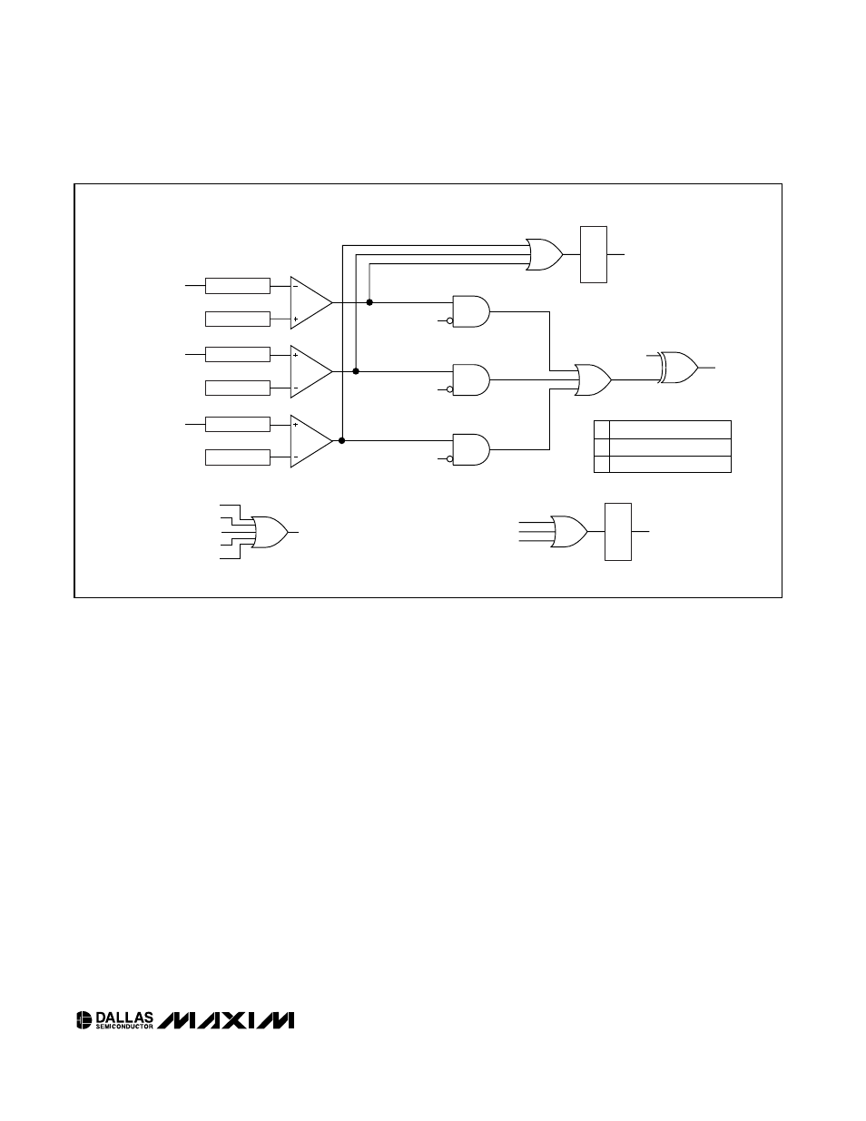
SHUTDOWN LOGIC
BMD (PIN)
(TX-P CURRENT)
BMD (PIN)
(TX-P CURRENT)
LOW TX-P MASK
HIGH TX-P MASK
QT LOW
TX-P FLAG
QT HIGH
TX-P FLAG
ADC
THRESHOLD
ADC
THRESHOLD
BIAS HIGH MASK
QT BIAS
HIGH FLAG
BIASSET (PIN)
(BIASSET CURRENT)
ADC
THRESHOLD
SOFT TX-D
P-DOWN/RST (PIN)
TX-D (PIN)
SHUTDOWN
FLAG
SAFETY FLAG
SOFT P-DOWN/RST
QT LOW TX-P FLAG
QT HIGH TX-P FLAG
SAFETY FLAG
FETG_POL
DRIVE A P-CHANNEL SWITCH
DRIVE A N-CHANNEL SWITCH
0
1
QT BIAS HIGH FLAG
LA
TCH
LATCHED-TX-FAULT
LA
TCH
FETG (PIN)
FETG_POL
Figure 12. Safety Fault and Shutdown Logic