Ds1862 xfp laser control and digital diagnostic ic, Table 2. temperature look-up table, Table 3. truth table for ten and aen bits – Rainbow Electronics DS1862 User Manual
Page 16
DS1862
XFP Laser Control and Digital Diagnostic IC
16
____________________________________________________________________
If the largest current range is selected, the maximum
value of FFh (from LUT) corresponds to a 1200µA sink
current. Regardless of current range, the MODSET
value always consists of 256 steps, including zero.
I
MODSET
can be controlled automatically with the tem-
perature-based look-up table, or by three other manual
methods.
Automatic temperature addressed look-up is accom-
plished by an internal or external temperature sensor
controlling an address pointer. This pointer indexes
through 127 previously loaded 8-bit current values
stored in the LUT. Each one of the 127 temperature
slot locations corresponds to a 2°C increment over
the -40°C to +102°C temperature range. Any tempera-
ture above or below these points causes the code in
the first or last temperature slot to be indexed. Both the
internal temperature sensor and an external sensor
connected to AUX2MON are capable of providing a
signal to control the extinction ratio automatically with
an indexed LUT. Table 2 illustrates the relationship
between the temperature and the memory locations in
the LUT.
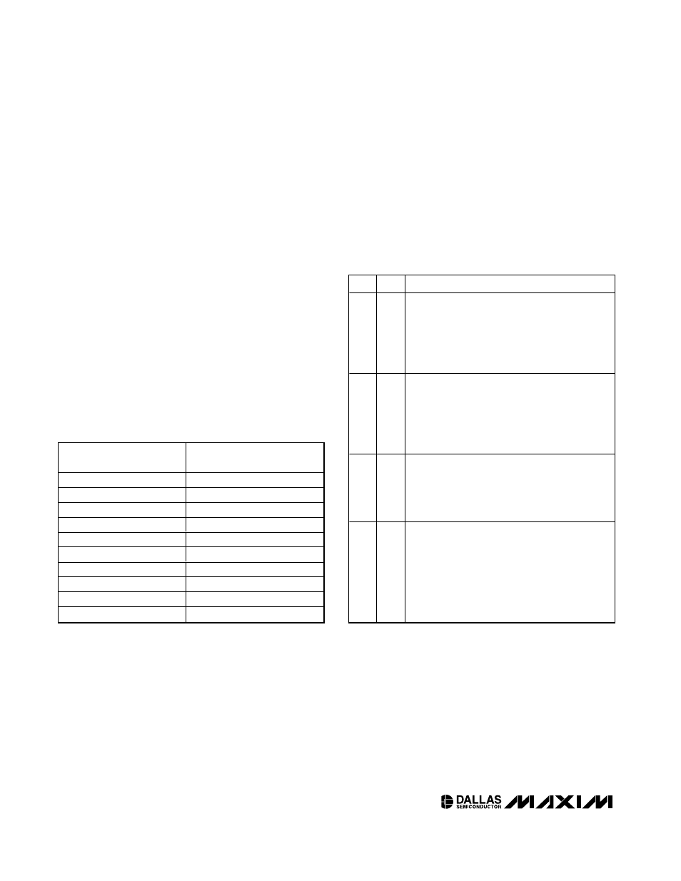
Automatic and manual control of MODSET is controlled
by two bits: TEN and AEN that reside in Table 04h, Byte
B2h. By default (from factory) TEN and AEN are both
set, causing complete automatic temperature-based
look-up. If TEN and/or AEN are altered, then the
DS1862 is set to one of the manual modes. Table 3
describes manual mode functionality.
Table 2. Temperature Look-Up Table
TEMPERATURE (°C)
CORRESPONDING LOOK-UP
TABLE ADDRESS
< -40
80h
-40
80h
-38
81h
-36
82h
—
—
+96
C4h
+98
C5h
+100
C6h
+102
C7h
> +102
C7h
Table 3. Truth Table for TEN and AEN Bits
TEN
AEN
DS1862 LUT FUNCTIONALITY
0
0
Manual mode that allows users to write a value
directly to the LUT Value register (Table 04h,
Byte B1h) to drive MODSET. While in this mode,
the LUT index pointer register is not being
updated, and no longer drives the LUT Value
register.
0
1
Manual mode that allows users to write a value
directly to the LUT Value register (Table 04h,
Byte B1h) to drive MODSET. While in this mode,
the LUT index pointer register is still being
updated, however it no longer drives the LUT
Value register.
1
0
Manual mode that allows users to write a value to
the LUT index pointer (Table 04h, Byte B0), then
the DS1862 updates the LUT Value register
(Table 04h, Byte B1h) based on the user’s index
pointer.
1
1
Automatic mode (factory default). This mode
automatically indexes the LUT based on
temperature, placing the resulting LUT address
in the LUT index pointer register (Table 04h, Byte
B0h). Then the MODSET setting is transferred
from that LUT address to the LUT Value register
(Table 04h, Byte B1h). Lastly the I
MODSET
is set
to the new MODSET code.