Rainbow Electronics 71M6542G User Manual
Data sheet, General description, Features
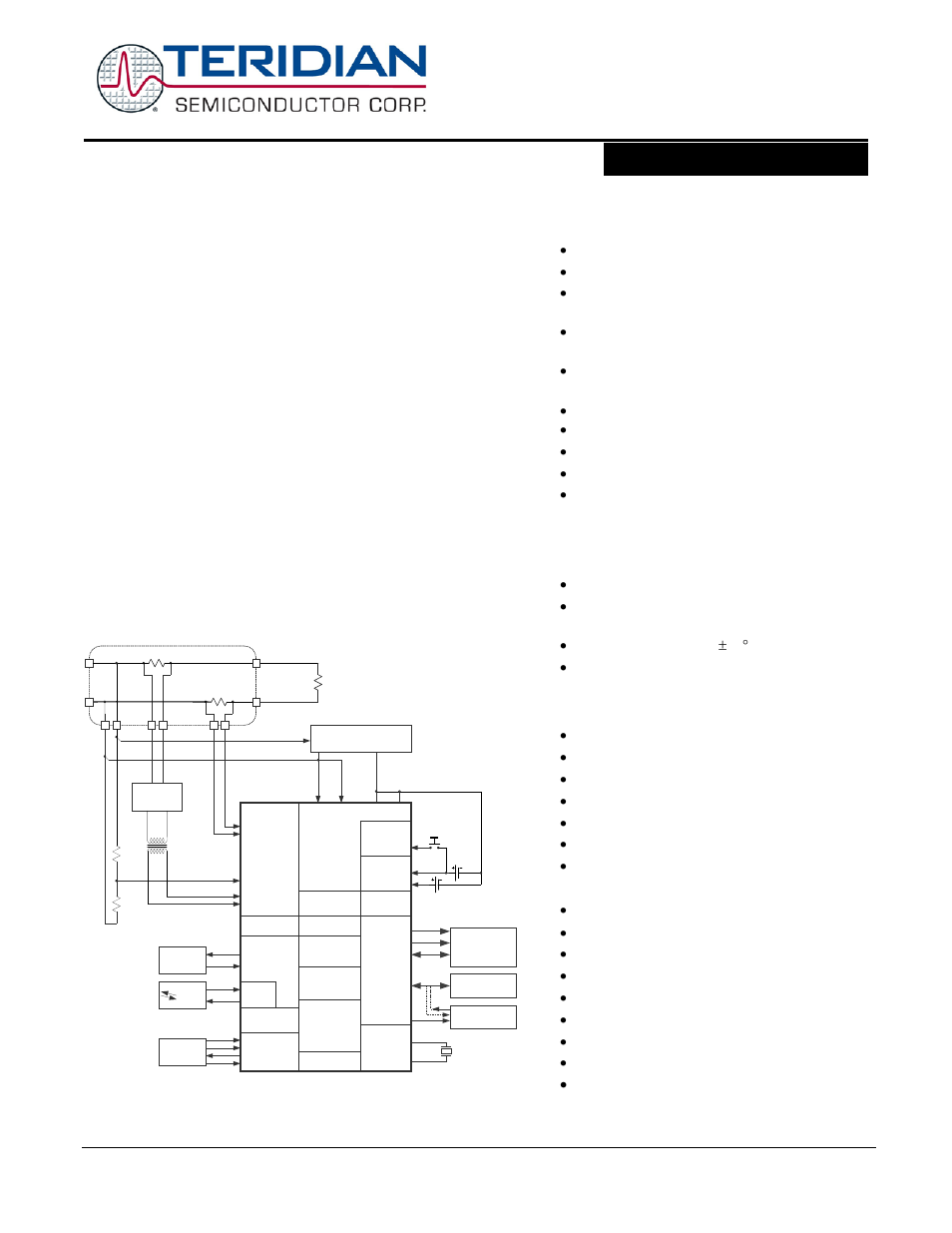
Table of contents
Document Outline
- 1 Introduction
- 2 Hardware Description
- 2.1 Hardware Overview
- 2.2 Analog Front End (AFE)
- 2.3 Digital Computation Engine (CE)
- 2.4 80515 MPU Core
- 2.5 On-Chip Resources
- 2.5.1 Physical Memory
- 2.5.2 Oscillator
- 2.5.3 PLL and Internal Clocks
- 2.5.4 Real-Time Clock (RTC)
- 2.5.5 71M654x Temperature Sensor
- 2.5.6 71M654x Battery Monitor
- 2.5.7 UART and Optical Interface
- 2.5.8 Digital I/O and LCD Segment Drivers
- 2.5.9 EEPROM Interface
- 2.5.10 SPI Slave Port
- 2.5.11 Hardware Watchdog Timer
- 2.5.12 Test Ports (TMUXOUT and TMUX2OUT Pins)
- 3 Functional Description
- 4 Application Information
- 4.1 Connecting 5 V Devices
- 4.2 Direct Connection of Sensors
- 4.3 71M6541D/F Using Local Sensors
- 4.4 71M6541D/F Using 71M6x01and Current Shunts
- 4.5 71M6542F Using Local Sensors
- 4.6 71M6542F Using 71M6x01 and Current Shunts
- 4.7 Metrology Temperature Compensation
- 4.8 Connecting I2C EEPROMs
- 4.9 Connecting Three-Wire EEPROMs
- 4.10 UART0 (TX/RX)
- 4.11 Optical Interface (UART1)
- 4.12 Connecting the Reset Pin
- 4.13 Connecting the Emulator Port Pins
- 4.14 Flash Programming
- 4.15 MPU Firmware Library
- 4.16 Crystal Oscillator
- 4.17 Meter Calibration
- 5 Firmware Interface
- 5.1 I/O RAM Map –Functional Order
- 5.2 I/O RAM Map – Alphabetical Order
- 5.3 CE Interface Description
- 6 Electrical Specifications
- 6.1 Absolute Maximum Ratings
- 6.2 Recommended External Components
- 6.3 Recommended Operating Conditions
- 6.4 Performance Specifications
- 6.4.1 Input Logic Levels
- 6.4.2 Output Logic Levels
- 6.4.3 Battery Monitor
- 6.4.4 Temperature Monitor
- 6.4.5 Supply Current
- 6.4.6 V3P3D Switch
- 6.4.7 Internal Power Fault Comparators
- 6.4.8 2.5 V Voltage Regulator – System Power
- 6.4.9 2.5 V Voltage Regulator – Battery Power
- 6.4.10 Crystal Oscillator
- 6.4.11 Phase-Locked Loop (PLL)
- 6.4.12 LCD Drivers
- 6.4.13 VLCD Generator
- 6.4.14 VREF
- 6.4.15 ADC Converter
- 6.4.16 Pre-Amplifier for IAP-IAN
- 6.5 Timing Specifications
- 6.6 Package Outline Drawings
- 6.7 Pinout Diagrams
- 6.8 Pin Descriptions
- 7 Ordering Information
- 8 Related Information
- 9 Contact Information
- Appendix A: Acronyms
- Appendix B: Revision History