Rainbow Electronics 71M6542G User Manual
Page 114
114
© 2008–2011 Teridian Semiconductor Corporation
v1.1
Name
Location
Rst Wk Dir Description
EX_XFER
EX_RTC1S
EX_RTC1M
EX_RTCT
EX_SPI
EX_EEX
EX_XPULSE
EX_YPULSE
EX_WPULSE
EX_VPULSE
2700[0]
2700[1]
2700[2]
2700[3]
2701[7]
2700[7]
2700[6]
2700[5]
2701[6]
2701[5]
0 0 R/W
Interrupt enable bits. These bits enable the XFER_BUSY, the RTC_1SEC,
etc. The bits are set by hardware and cannot be set by writing a 1. The bits
are reset by writing 0. Note that if one of these interrupts is to enabled, its
corresponding 8051 EX enable bit must also be set. See
details.
EW_DIO4
28B3[2]
0 – R/W
Connects SEGDIO4 to the WAKE logic and permits SEGDIO4 rising to wake
the part. This bit has no effect unless DIO4 is configured as a digital input.
EW_DIO52
28B3[1]
0 – R/W
Connects SEGDIO52 to the WAKE logic and permits SEGDIO52 rising to
wake the part. This bit has no effect unless SEGDIO52 is configured as a
digital input.
The SEGDIO52 pin is only available in the 71M6542F.
EW_DIO55
28B3[0]
0 – R/W
Connects SEGDIO55 to the WAKE logic and permits SEGDIO55 rising to
wake the part. This bit has no effect unless SEGDIO55 is configured as a
digital input.
EW_PB
28B3[3]
0 – R/W
Connects PB to the WAKE logic and permits PB rising to wake the part. PB
is always configured as an input.
EW_RX
28B3[4]
0 – R/W
Connects RX to the WAKE logic and permits RX rising to wake the part. See
the WAKE description on page 87 for de-bounce issues.
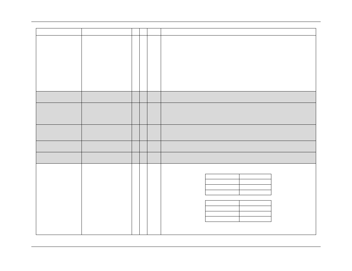
FIR_LEN[1:0]
210C[2:1]
0 0 R/W
Determines the number of ADC cycles in the ADC decimation FIR filter.
PLL_FAST = 1:
FIR_LEN[1:0]
ADC Cycles
00
141
01
288
10
384
PLL_FAST = 0:
FIR_LEN[1:0]
ADC Cycles
00
135
01
276
10
Not Allowed
The ADC LSB size and full-scale values depend on the FIR_LEN[1:0] setting.
Refer to