4 performance specifications, 1 input logic levels, 2 output logic levels – Rainbow Electronics 71M6542G User Manual
Page 140: Performance specifications, Input logic levels, Output logic levels, Table 97: input logic levels, Table 98: output logic levels
140
© 2008–2011 Teridian Semiconductor Corporation
v1.1
6.4
Performance Specifications
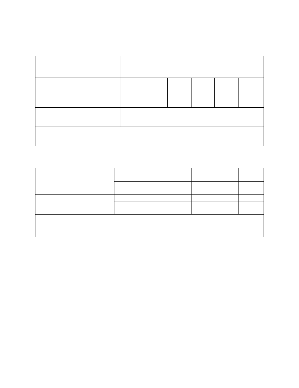
6.4.1 Input Logic Levels
Table 96: Input Logic Levels
Parameter
Condition
Min
Typ
Max
Unit
Digital high-level input voltage
1
, V
IH
2
V
Digital low-level input voltage
1
, V
IL
0.8
V
Input pullup current, I
IL
E_RXTX, E_RST, E_TCLK
OPT_RX, OPT_TX
SPI_CSZ (SEGDIO36)
Other digital inputs
VIN=0 V,
ICE_E=3.3 V
10
10
10
-1
0
100
100
10
1
µA
µA
µ
Ω
µA
Input pull down current, I
IH
ICE_E, RESET, TEST
Other digital inputs
VIN=V3P3D
10
-1
0
100
1
µA
µA
Note:
1. In battery powered modes, digital inputs should be below 0.1 V or above VBAT – 0.1 V to
minimize battery current.
6.4.2 Output Logic Levels
Table 97: Output Logic Levels
Parameter
Condition
Min
Typ
Max
Unit
Digital high-level output voltage
V
OH
I
LOAD
= 1 mA
V3P3D–0.4
V
I
LOAD
= 15 mA
(see notes 1, 2)
V3P3D-0.6
V
Digital low-level output voltage
V
OL
I
LOAD
= 1 mA
0
0.4
V
I
LOAD
= 15 mA
(see note 1)
0
0.8
V
Note:
1. Guaranteed by design, not production tested.
2. Caution: The sum of all pull up currents must be compatible with the on-resistance of the
internal V3P3D switch. See