11 ce calibration parameters, Ce calibration parameters, Table 93: ce calibration parameters – Rainbow Electronics 71M6542G User Manual
Page 135: Aa 2
v1.1
© 2008–2011 Teridian Semiconductor Corporation
135
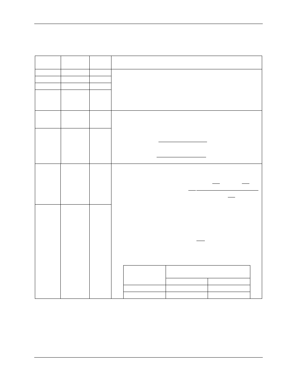
5.3.11 CE Calibration Parameters
lists the parameters that are typically entered to effect calibration of meter accuracy.
Table 92: CE Calibration Parameters
CE
Address
Name
Default Description
0x10
CAL_IA
16384
These constants control the gain of their respective channels. The
nominal value for each parameter is 2
14
= 16384. The gain of each
channel is directly proportional to its CAL parameter. Thus, if the
gain of a channel is 1% slow, CAL should be increased by 1%.
Refer to the 71M6541 Demo Board User’s Manual for the equations
to calculate these calibration parameters.
†
71M6542 only.
0x11
CAL_VA
16384
0x13
CAL_IB
16384
0x14
†
CAL_VB
16384
0x12
PHADJ_A
0
These constants control the CT phase compensation. Compensation
does not occur when PHADJ_X = 0. As PHADJ_X is increased,
more compensation (lag) is introduced. The range is
± 215 – 1. If
it is desired to delay the current by the angle
Φ, the equations are:
Φ
⋅
−
Φ
⋅
=
TAN
TAN
X
PHADJ
0131
.
0
1487
.
0
02229
.
0
2
_
20
at 60Hz
Φ
⋅
−
Φ
⋅
=
TAN
TAN
X
PHADJ
009695
.
0
1241
.
0
0155
.
0
2
_
20
at 50Hz
0x15
PHADJ_B
0
0x12
DLYADJ_A
0
The shunt delay compensation is obtained using the equation
provided below:
(
)
+
+
∆
+
∆
=
s
s
s
rees
rees
f
f
c
b
f
f
ab
f
f
a
X
DLYADJ
π
π
π
π
2
sin
2
cos
2
2
cos
360
2
2
1
.
0
1
_
2
2
14
deg
deg
where:
A
a
2
=
1
2
+
= A
b
𝑐 = 2𝐴
2
+ 4𝐴𝑐𝑜𝑠 �
2𝜋𝑓
𝑓
𝑠
� + 2
Where, f is the mains frequency and f
s
is the sampling frequency.
The table below provides the value of A for each current channel:
Channel
Value of A
(decimal)
Eq. 0 or 2
Eq. 1
DLYADJ_A
15811 / 2
14
6811 / 2
14
DLYADJ_B
-1384 / 2
14
-1384 / 2
14
0x15
DLYADJ_B
0