4 application information, 1 connecting 5 v devices, 2 direct connection of sensors – Rainbow Electronics 71M6542G User Manual
Page 92: Application information, Connecting 5 v devices, Direct connection of sensors, 4application information
92
© 2008–2011 Teridian Semiconductor Corporation
v1.1
4
Application Information
4.1
Connecting 5 V Devices
All digital input pins of the 71M654x are compatible with external 5 V devices. I/O pins configured as
inputs do not require current-limiting resistors when they are connected to external 5 V devices.
4.2
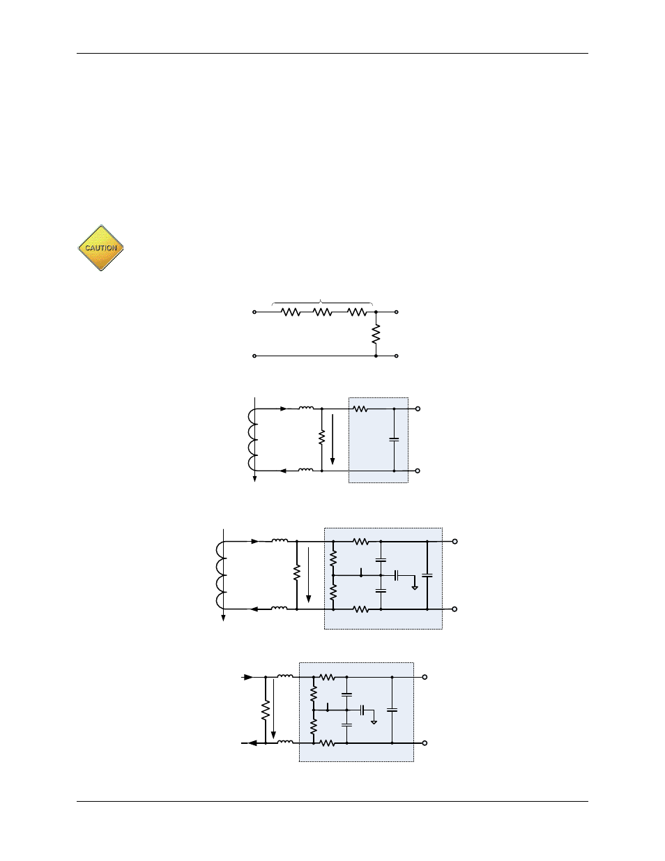
Direct Connection of Sensors
through
show voltage-sensing resistive dividers, current-sensing current transformers
(CTs) and current-sensing resistive shunts and how they are connected to the voltage and current inputs
of the 71M654x. All input signals to the 71M654x sensor inputs are voltage signals providing a scaled
representation of either a sensed voltage or current.
The analog input pins of the 71M654x are designed for sensors with low source impedance.
RC filters with resistance values higher than those implemented in the Teridian Demo Boards
must not be used. Please refer to the Demo Board schematics for complete sensor input
circuits and corresponding component values.
R
IN
V
IN
R
OUT
V3P3A
VA
Figure 31: Resistive Voltage Divider (Voltage Sensing)
I
IN
IAP
V3P3A
V
OUT
I
OUT
R
BURDEN
CT
1:N
Noise Filter
Figure 32. CT with Single-Ended Input Connection (Current Sensing)
I
IN
IAP
IAN
V3P3A
V
OUT
I
OUT
R
BURDEN
CT
1:N
Bias Network and Noise Filter
Figure 33: CT with Differential Input Connection (Current Sensing)
I
IN
R
SHUNT
IAP
IAN
V3P3A
V
OUT
Bias Network and Noise Filter
Figure 34: Differential Resistive Shunt Connections (Current Sensing)