Table 68: available circuit functions, Table 67 – Rainbow Electronics 71M6542G User Manual
Page 82
82
© 2008–2011 Teridian Semiconductor Corporation
v1.1
Transitions from both LCD and SLP mode to BRN mode can be initiated by the following events:
• Wake-up timer timeout.
• Pushbutton (PB) is activated.
• A rising edge on SEGDIO4, SEGDIO52 (71M6542F only) or SEGDIO55.
• Activity on the RX or OPT_RX pins.
The MPU has access to a variety of registers that signal the event that caused the wake up. See
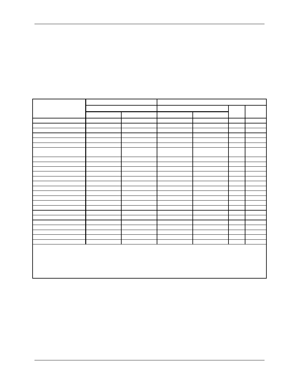
shows the circuit functions available in each operating mode.
Table 67: Available Circuit Functions
Circuit Function
System Power
Battery Power
MSN (Mission Mode)
BRN (Brownout Mode)
LCD
SLEEP
PLL_FAST=1 PLL_FAST=0 PLL_FAST=1 PLL_FAST=0
CE (Computation Engine)
Yes
Yes
Note 1
Note 1
--
2
--
FIR
Yes
Yes
--
--
--
--
ADC, VREF
Yes
Yes
--
--
--
--
PLL
Yes
Yes
Yes
Yes
Boost
2
--
Battery Measurement
Yes
Yes
Yes
Yes
--
--
Temperature sensor
Yes
Yes
Yes
Yes
Yes
Yes
Max MPU clock rate
4.92MHz
(from PLL)
1.57MHz
(from PLL)
4.92MHz
(from PLL)
1.57MHz
(from PLL)
--
--
MPU_DIV clk. divider
Yes
Yes
Yes
Yes
--
--
ICE
Yes
Yes
Yes
Yes
--
--
DIO Pins
Yes
Yes
Yes
Yes
--
--
Watchdog Timer
Yes
Yes
Yes
Yes
--
--
LCD
Yes
Yes
Yes
Yes
Yes
--
LCD Boost
Yes
Yes
Yes
Yes
Yes
EEPROM Interface (2-wire)
Yes
Yes
Yes
Yes
--
--
EEPROM Interface (3-wire)
Yes
Yes
Yes
Yes
--
--
UART (full speed)
Yes
Yes
Yes
Yes
--
--
Optical TX modulation
38.4kHz
38.9kHz
38.4kHz
38.9kHz
--
--
Flash Read
Yes
Yes
Yes
Yes
--
--
Flash Page Erase
Yes
Yes
Yes
Yes
--
--
Flash Write
Yes
Yes
Yes
Yes
--
--
RAM Read and Write
Yes
Yes
Yes
Yes
--
--
Wakeup Timer
Yes
Yes
Yes
Yes
Yes
Yes
OSC and RTC
Yes
Yes
Yes
Yes
Yes
Yes
DRAM data preservation
Yes
Yes
Yes
Yes
--
--
NV RAM data preservation
Yes
Yes
Yes
Yes
Yes
Yes
Notes:
1.
The CE is active in BRN mode, but ADC data is inaccurate. The MPU should halt the CE to conserve power (CE_E = 0,
I/O RAM 0x2106[0]).
2.
“--“ indicates that the corresponding circuit is not active
3.
“Boost” implies that the LCD boost circuit is active (i.e., LCD_VMODE[1:0] = 10 (I/O RAM 0x2401[7:6]). The LCD boost
circuit requires a clock from the PLL to function. Thus, the PLL is automatically kept active if LCD boost is active while in
LCD mode, otherwise the PLL is de-activated.