Rainbow Electronics 71M6542G User Manual
Page 117
v1.1
© 2008–2011 Teridian Semiconductor Corporation
117
Name
Location
Rst Wk Dir Description
LCD_MAP[55:48]
LCD_MAP[47:40]
LCD_MAP[39:32]
LCD_MAP[31:24]
LCD_MAP[23:16]
LCD_MAP[15:8]
LCD_MAP[7:0]
2405[7:0]
2406[7:0]
2407[7:0]
2408[7:0]
2409[7:0]
240A[7:0]
240B[7:0]
0
0
0
0
0
0
0
–
–
–
–
–
–
–
R/W
R/W
R/W
R/W
R/W
R/W
R/W
Enables LCD segment driver mode of combined SEGDIO pins. Pins that
cannot be configured as outputs (SEG48 through SEG50) become inputs with
internal pull ups when their LCD_MAP bit is zero. Also, note that SEG48
through SEG50 are multiplexed with the in-circuit emulator signals. When the
ICE_E pin is high, the ICE interface is enabled, and SEG48 through SEG50
become E_RXTX, E_TCLK and E_RST, respectively.
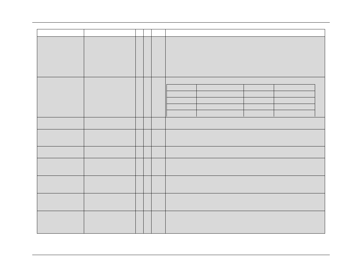
LCD_MODE[2:0]
2400[6:4]
0 – R/W
Selects the LCD bias and multiplex mode.
LCD_MODE
Output
LCD_MODE
Output
000
4 states, 1/3 bias
100
Static display
001
3 states, 1/3 bias
101
5 states, 1/3 bias
010
2 states, ½ bias
110
6 states, 1/3 bias
011
3 states, ½ bias
LCD_ON
LCD_BLANK
240C[0]
240C[1]
0
0
–
–
R/W
R/W
Turns on or off all LCD segments without changing LCD data. If both bits are
set, the LCD display is turned on.
LCD_ONLY
28B2[6]
0 0
W
Puts the IC to sleep, but with LCD display still active. Ignored if system power
is present. It awakens when Wake Timer times out, when certain DIO pins
are raised, or when system power returns. See
LCD_RST
240C[2]
0 – R/W
Clear all bits of LCD data. These bits affect SEGDIO pins that are configured
as LCD drivers. This bit does not auto clear.
LCD_SEG0[5:0]
to
LCD_SEG15[5:0]
2410[5:0] to
241F[5:0]
0 – R/W
SEG Data for SEG0 through SEG15. DIO data for these pins is in SFR
space.
LCD_SEGDIO16[5:0]
to
LCD_SEGDIO45[5:0]
2420[5:0] to
243D[5:0]
0 – R/W
SEG and DIO data for SEGDIO16 through SEGDIO45. If configured as DIO,
bit 1 is direction (1 is output, 0 is input), bit 0 is data, and the other bits are
ignored.
LCD_SEG46[5:0]
to
LCD_SEG50[5:0]
243E[5:0] to 2442[5:0] 0 – R/W
SEG data for SEG46 through SEG50. These pins cannot be configured as
DIO.
LCD_SEGDIO51[5:0]
to
LCD_SEGDIO55[5:0]
2443[5:0] to 2447[5:0]
0 – R/W
SEG and DIO data for SEGDIO51 through SEGDIO55. If configured as DIO,
bit 1 is direction (1 is output, 0 is input), bit 0 is data, and the other bits are
ignored.
SEGDIO52 through SEDIO54 are available only on the 71M6542F.