Rainbow Electronics 71M6542G User Manual
Page 13
v1.1
© 2008–2011 Teridian Semiconductor Corporation
13
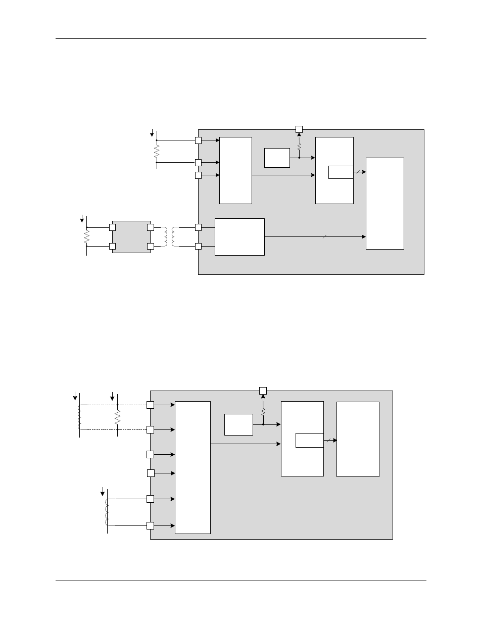
shows the 71M6541D/F multiplexer interface with one local and one remote resistive shunt
sensor. As seen in
, when a remote isolated shunt sensor is connected via the 71M6x01, the
samples associated with this current channel are not routed to the multiplexer, and are instead
transferred digitally to the 71M6541D/F via the digital isolation interface and are directly stored in CE
RAM.
See
for the multiplexer timing sequence corresponding to
configurations corresponding to
∆Σ ADC
CONVERTER
VREF
MUX
VREF
VREF
VADC
22
FIR
IBP
IAP
VADC10 (VA)
IAN
IBN
71M6541D/F
CE RAM
71M6x01
SP
SN
INP
INN
Remote
Shunt
IN*
Digital
Isolation
Interface
Local
Shunt
I
LINE
22
11/5/2010
* IN = Optional Neutral Current
Figure 3. 71M6541D/F AFE Block Diagram with 71M6x01
shows the 71M6542F AFE with locally connected sensors. The analog input signals (IAP-IAN,
VA, IBP-IBN and VB) are multiplexed to the ADC input and sampled by the ADC. The ADC output is
decimated by the FIR filter and stored in CE RAM where it can be accessed and processed by the CE.
See
for the multiplexer timing sequence corresponding to
configuration corresponding to
∆Σ ADC
CONVERTER
VREF
MUX
VREF
VREF
VADC
22
FIR
IBP
IAP
VADC10 (VA)
IAN
IBN
71M6542F
CE RAM
Local
Shunt
IB
CT
IA
or
CT
11/5/2010
IA
VADC9 (VB)
Figure 4. 71M6542F AFE Block Diagram (Local Sensors)