Table 64: spi command sequences, Figure 27 – Rainbow Electronics 71M6542G User Manual
Page 75
v1.1
© 2008–2011 Teridian Semiconductor Corporation
75
A15
A14
A1
A0
C0
0
31
x
D6
D1
D0
D7
D6
D1
D0
C5
C6
C7
(From Host) SPI_CSZ
(From Host) SPI_CK
(From Host) SPI_DI
(From 654x) SPI_DO
8 bit CMD
16 bit Address
DATA[ADDR]
DATA[ADDR+1]
15
16
23
24
32
39
Extended Read . . .
SERIAL READ
A15
A14
A1
A0
C0
C5
C6
C7
x
8 bit CMD
16 bit Address
DATA[ADDR]
DATA[ADDR+1]
Extended Write . . .
SERIAL WRITE
D6
D1
D0
D7
D6
D1
D0
x
HI Z
HI Z
Status Byte
ST7
ST6
ST5
ST0
D7
40
47
0
31
15
16
23
24
32
39
40
47
Status Byte
D7
ST7
ST6
ST5
ST0
(From Host) SPI_CSZ
(From Host) SPI_CK
(From Host) SPI_DI
(From 654x) SPI_DO
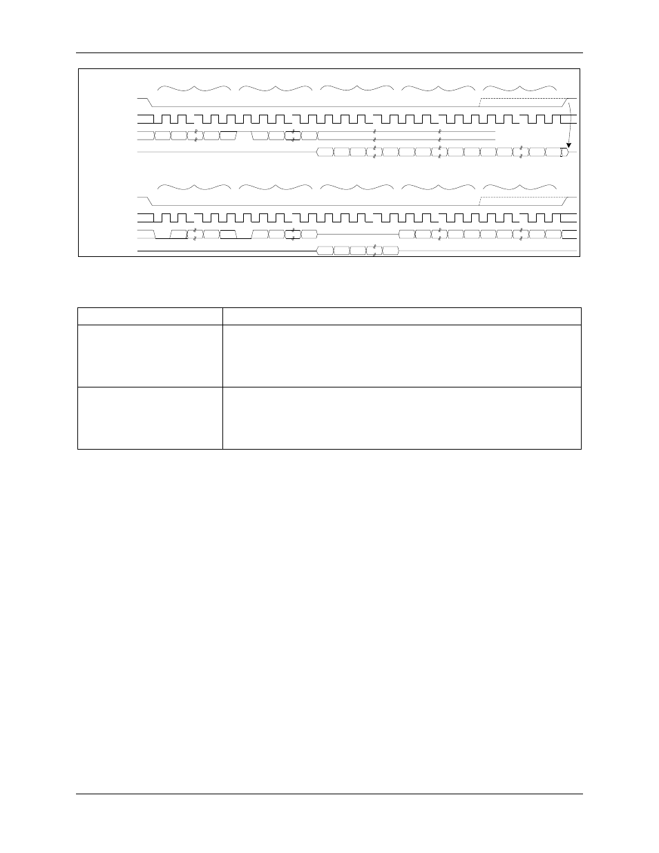
Figure 27: SPI Slave Port - Typical Multi-Byte Read and Write operations
Table 63: SPI Command Sequences
Command Sequence
Description
ADDR 1xxx xxxx STATUS
Byte0 ... ByteN
Read data starting at ADDR. ADDR auto-increments until SPI_CSZ is
raised. Upon completion, SPI_CMD (SFR 0xFD) is updated to 1xxx xxxx
and an SPI interrupt is generated. The exception is if the command byte
is 1000 0000. In this case, no MPU interrupt is generated and SPI_CMD
is not updated.
0xxx xxxx ADDR Byte0 ...
ByteN
Write data starting at ADDR. ADDR auto-increments until SPI_CSZ is
raised. Upon completion, SPI_CMD is updated to 0xxx xxxx and an SPI
interrupt is generated. The exception is if the command byte is 0000
0000. In this case, no MPU interrupt is generated and SPI_CMD is not
updated.