Rf22 – Rainbow Electronics RF22 User Manual
Page 59
RF22
Version: 0.1 Date: 12/23/2008
Tel: +86-755-82973805 Fax: +86-755-82973550 E-mail: [email protected] http://www.hoperf.com
59
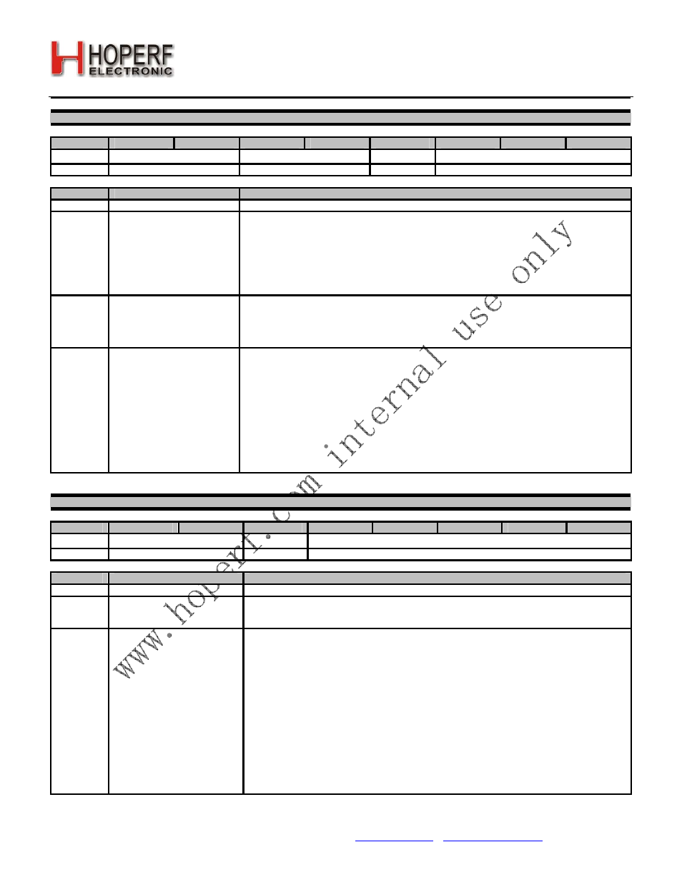
Register 0Ah. Microcontroller Output Clock
Bit
D7
D6
D5
D4
D3
D2
D1
D0
Name
Reserved
clkt[1:0]
enlfc
mclk[2:0]
Type
R
R/W
R/W
R/W
Reset value = xx000110
Bit
Name
Function
7:6
Reserved
Reserved.
5:4
clkt[1:0]
Clock Tail.
If enlfc = 0 then it can be useful to provide a few extra cycles for the microcontroller to complete
its operation. Setting the clkt[1:0] register will provide the addition cycles of the clock before it
shuts off.
00: 0 cycle
01: 128 cycles
10: 256 cycles
11: 512 cycles
3
enlfc
Enable Low Frequency Clock.
When enlfc = 1 and the chip is in Sleep mode then the 32.768 kHz clock will be provided to the
microcontroller no matter what the selection of mclk[2:0] is. For example if mclk[2:0] = ‘000’,
30MHz will be available through the GPIO to output to the microcontroller in all Idle, TX, or RX
states. When the chip is commanded to Sleep mode the 30 MHz clock will become 32.768 kHz.
2:0
mclk[2:0]
Microcontroller Clock.
Different clock frequencies may be selected for configurable GPIO clock output. All clock
frequencies are created by dividing the XTAL except for the 32 kHz clock which comes directly
from the 32 kHz RC Oscillator. The mclk[2:0] setting is only valid when xton = 1 except the 111.
000: 30 MHz
001: 15 MHz
010: 10 MHz
011: 4 MHz
100: 3 MHz
101: 2 MHz
110: 1 MHz
111: 32.768 kHz
Register 0Bh. GPIO Configuration 0
Bit
D7
D6
D5
D4
D3
D2
D1
D0
Name
gpiodrv0[1:0]
pup0
gpio0[4:0]
Type
R/W
R/W
R/W
Reset value = 00000000
Bit
Name
Function
7:6
gpiodrv0[1:0]
GPIO Driving Capability Setting.
5
pup0
Pullup Resistor Enable on GPIO0.
When set to 1 a 200 kΩ resistor is connected internally between VDD and the pin if the GPIO is
configured as a digital input.
4:0
gpio0[4:0]
GPIO0pin Function Select.
00000: Power-On-Reset (output)
00001: Wake-Up Timer: 1 when WUT has expired (output)
00010: Low Battery Detect: 1 when battery is below threshold setting (output)
00011: Direct Digital Input
00100: External Interrupt, falling edge (input)
00101: External Interrupt, rising edge (input)
00110: External Interrupt, state change (input)
00111: ADC Analog Input
01000: Reserved (Analog Test N Input)
01001: Reserved (Analog Test P Input)
01010: Direct Digital Output
01011: Reserved (Digital Test Output)
01100: Reserved (Analog Test N Output)
01101: Reserved (Analog Test P Output)
01110: Reference Voltage (output)