Rf22 – Rainbow Electronics RF22 User Manual
Page 15
RF22
Version: 0.1 Date: 12/23/2008
Tel: +86-755-82973805 Fax: +86-755-82973550 E-mail: [email protected] http://www.hoperf.com
15
3.2.9.3. Automatic Frequency Change
If registers 79h or 7Ah are changed in either TX or RX mode, then the state machine will automatically transition the
chip back to tune, change the frequency, and automatically go back to either TX or RX. This feature is useful to reduce
the number of SPI commands required in a Frequency Hopping System. This in turn reduces microcontroller activity,
reducing current consumption.
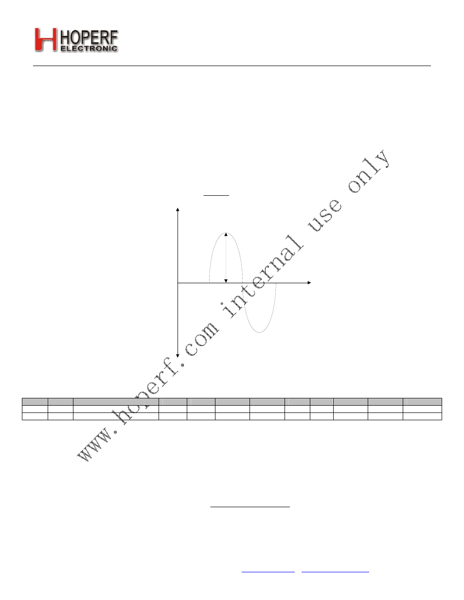
3.2.9.4. Frequency Deviation
The peak frequency deviation is configurable from ±1 to ±320 kHz. The Frequency Deviation (Δf) is controlled by the
Frequency Deviation Register (fd), address 71 and 72h, and is independent of the carrier frequency setting. When
enabled, regardless of the setting of the hbsel bit (high band or low band), the resolution of the frequency deviation will
remain in increments of 625 Hz. When using frequency modulation the carrier frequency will deviate from the nominal
center channel carrier frequency by +/- Δf:
[ ]
Hz
fd
f
625
0
:
8
×
=
Δ
[ ]
Hz
f
fd
625
0
:
8
Δ
=
Δf=peak deviation
F
req
uency
f
TX
Time
Δf
The previous equation should be used to calculate the desired frequency deviation. If desired, frequency modulation
may also be disabled in order to obtain an unmodulated carrier signal at the channel center frequency; see "4.1.
Modulation Type" on page 32 for further details.
Add
R/W
Function/Description
D7
D6
D5
D4
D3
D2
D1
D0
POR Def.
71
R/W
Modulation Mode Control 2
trclk[1]
trclk[0]
dtmod[1]
dtmod[0]
eninv
fd[8]
modtyp[1] modtyp[0]
00h
72
R/W
Frequency
Deviation fd[7]
fd[6]
fd[5] fd[4] fd[3]
fd[2]
fd[1] fd[0] 43h
3.2.9.5. Frequency Offset Adjustment
When the AFC is disabled the Frequency offset can be adjusted manually by fo[9:0] in registers 73h and 74h. The
Frequency offset adjustment and the AFC both are implemented by shifting the Synthesizer Local Oscillator frequency.
This register is a signed register so in order to get a negative offset you will need to take the twos complement of the
positive offset number. The offset can be calculated by the following:
(
)
[ ]
0
:
9
1
25
.
156
fo
hbsel
Hz
set
DesiredOff
Ч
+
Ч
=
[ ]
(
)
1
25
.
156
0
:
9
+
Ч
=
hbsel
Hz
set
DesiredOff
fo
The adjustment range in high band is: ±160 kHz, and adjustment range in low band is: ±80 kHz. For example to
compute an offset of +50 kHz in high band mode fo[9:0] should be set to 0A0h. For an offset of –50 kHz in high band