Rf22, Temperature sensor – Rainbow Electronics RF22 User Manual
Page 37
RF22
Version: 0.1 Date: 12/23/2008
Tel: +86-755-82973805 Fax: +86-755-82973550 E-mail: [email protected] http://www.hoperf.com
37
The gain is different for different VDD dependent references so the reference change has no influence on input range and digital
measured values.
The differential offset can be coarse compensated by the adcoffs[3:0] bits found in "Register 11h. ADC Value". Fine
compensation should be done by the microcontroller software. The main reason for the offset compensation is to shift
the negative offset voltage of the bridge sensor to the positive differential voltage range. This is essential as the
differential input mode is unipolar. The offset compensation is VDD proportional, so the VDD change has no influence
on the measured value.
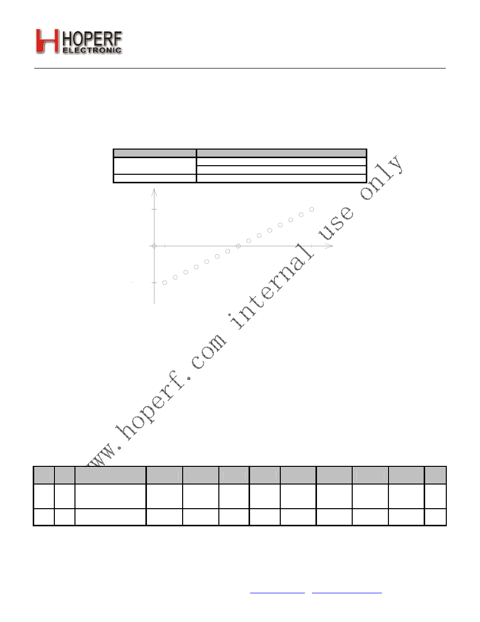
adcoffs[3]
Input Offset (% of VDD)
0 if adcoffs[2:0] = 0
0
–(8 – adcoffs[2:0]) x 0.12
1
adcoffs[2:0] x 0.12
0.84 %
0.84 %
0 %
0
15
Input Offset
adcoffs[3:0]
8
1
Figure25. ADC Differential Input Offset for Sensor Offset Coarse Compensation
8.4. Temperature Sensor
An analog temperature sensor is integrated into the chip. The temperature sensor will be automatically enabled when
the temperature sensor is selected as the input of the ADC or when the analog temp voltage is selected on the analog
test bus. The temperature sensor value may be digitized using the general-purpose ADC and read out over the SPI
through "Register 10h. ADC Sensor Amplifier Offset". The range of the temperature sensor is selectable to configure to
the desired application and performance. The table below demonstrates the settings for the different temperature
ranges and performance. To use the Temp Sensor:
1. Set input for ADC to be Temperature Sensor, "Register 0Fh. ADC Configuration"—adcsel[2:0] = 000
2. Set Reference for ADC, "Register 0Fh. ADC Configuration"—adcref[1:0] = 00
3. Set Temperature Range for ADC, "Register 12h. Temperature Sensor Calibration"—tsrange[1:0]
4. Set entsoffs = 1, "Register 12h. Temperature Sensor Calibration"
5. Trigger ADC Reading, "Register 0Fh. ADC Configuration"—adcstart = 1
6. Read-out Value—Read Address in "Register 11h. ADC Value"
Add R/W Function/Description
D7
D6
D5
D4
D3
D2
D1
D0
POR
Def.
12 R/W
Temperature Sensor
Control
tsrange[1]
tsrange[0] entsoffs entstrim vbgtrim[3] vbgtrim[2]
vbgtrim[1] vbgtrim[0] 20h
13 R/W
Temperature Value
Offset
tvoffs[7]
tvoffs[6]
tvoffs[5] tvoffs[4] tvoffs[3] tvoffs[2]
tvoffs[1]
tvoffs[0]
00h